Introduction
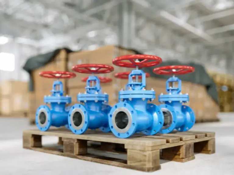
The gate valve is still the most common isolation mechanism in the complicated infrastructure of industrial fluid dynamics. The gate valve is used in a binary mode, unlike other types of valves that are used to modulate the flow of fluid: the valve is either completely open to permit the free flow of fluid or completely closed to isolate a part of the pipeline. The dependability of this element is not only based on its overall classification but also on the exact engineering of its internal components and the metallurgical soundness of its production process.
A shallow knowledge of the gate valves is not enough for engineers, procurement managers, and maintenance technicians. The peculiarities of the work of the valve parts, the peculiarities of the valve design, and the importance of the quality of casting are the aspects that should be known to guarantee the best performance and durability of the valve. This manual offers a strict analysis of the standard gate valve, breaking down its structure, functional differences, and the quality standards that must be met to withstand high pressure and severe environments.
How a Gate Valve Works: A Quick Overview
A gate valve works linearly. A gate or disc is a barrier that flows perpendicular to the fluid flow. In the fully open position of the valve, the gate is completely withdrawn into the bonnet, and the flow path is clear. This straight-through design causes a low pressure loss and a low coefficient of flow resistance, which is a clear advantage over globe valves, which require the fluid to change direction, resulting in an increased pressure drop.
The gate valves are purely isolation valves. They are not throttling designs. With a partially open gate valve, the high-velocity fluid will strike the gate and the valve seat, resulting in vibration, cavitation, and erosion of the sealing surface at a high rate. Whereas ball valves and butterfly valves have faster actuation (quarter-turn), gate valves have slow actuation. This multi-turn is a mechanical benefit, since it eliminates the hydraulic shock (water hammer) that may cause damage to piping systems.
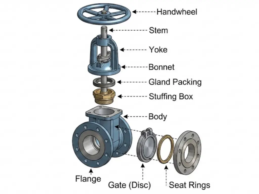
Detailed Anatomy: The 5 Key Components of a Gate Valve
In order to assess the quality of a valve, it is necessary to examine how its parts are assembled. The design of a normal gate valve may be divided into the shell that holds the pressure and the functional trim.
The Body and Bonnet (The Shell)
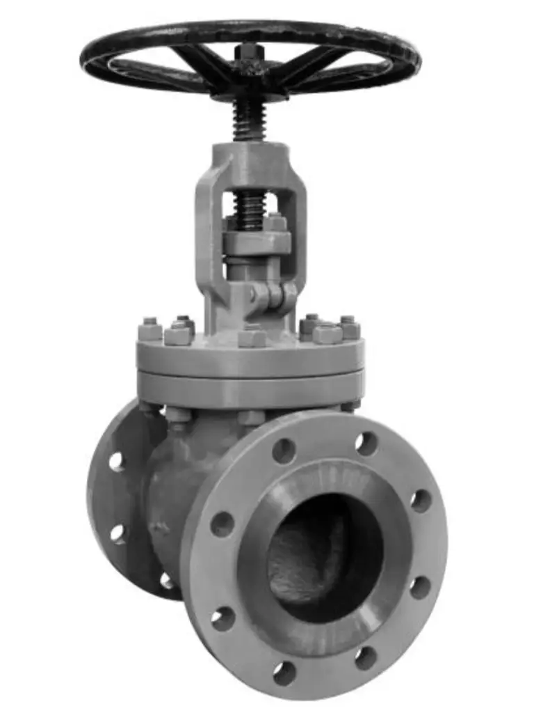
The main pressure boundary of the device is the valve body. It is attached to the pipeline through flanged, screwed, or welded ends and contains the internal parts. The geometry of the body is of paramount importance; it should be able to withstand the system pressure without deformation, which would lead to the loss of the seal. The body is typically made of carbon steel, which is used in general utility, and stainless steel, which is used in applications that demand high levels of corrosion resistance.
The valve bonnet is connected to the body. The bonnet serves as a shield to the hole in the body and gives a secondary pressure boundary. It helps to hold the stem and the actuator. The body-bonnet joint is a critical potential leak point, and must be sealed with a proper seal using gaskets or pressure-seal mechanisms based on the service rating.
With the help of Bessercast‘s patented technology, BesserCast is capable of producing exact and highly detailed valve bodies whose lead times, quality, and defect percentages surpass the competition using traditional sand casting methods. Contact us to improve your next project BesserCast’s certified valve bodies designed to resist corrosion with close tolerances and capable of yielding high pressures.
The Valve Trim (Disc, Seat, and Stem)
In industrial valve terminology, the “trim” refers to the internal parts exposed to the process medium.
- Valve Gate (Disc): This is the closing element. Its precision is paramount. Even a surface finish variation of a few micrometers can not allow a tight seal.
- Valve Seat: The seats provide the stationary sealing surface against which the gate rests. In many industrial valves, metal seats are preferred for their durability in high temperatures and abrasive environments. These seats may be integral to the valve body or threaded/welded rings (renewable seats).
- Valve Stem: The stem is the transmission shaft that connects the handwheel or actuator to the gate. It converts the rotational torque applied by the operator into the linear force required to seat or unseat the gate against the differential pressure.
Actuator and Gland Packing
The actuator often has a hand wheel and a stem nut, also known as the yoke sleeve. The hand wheel, when turned, rotates the stem nut, which drives the stem that is threaded.
To prevent any fluid that is flowing along the stem from leaking, a seal construction known as stem packing is used. Stem packing consists of fibrous materials that are PTFE and graphite, which are compressed in the stuffing box by the gland flange. Stem packing needs to be kept at the right compression. If the stem packing is too loose, then the valve will leak. If the stem packing is too tight, then the stem packing will provide friction, which will not allow the valve stem to move.
| Component | Primary Function | Typical Materials | Critical Quality Requirements | Common Failure Modes |
| Body | Serves as the main pressure-containing shell and houses the internal trim components. | Carbon steel, stainless steel, alloy steel, ductile iron | Must withstand system pressure without deformation; defect-free casting; uniform wall thickness; precise machining of seating areas. | Cracking from casting porosity, corrosion, erosion, external leakage from body defects. |
| Bonnet | Provides the upper enclosure of the valve and supports the stem and packing assembly. | Carbon steel, stainless steel, forged steel | Leak-tight body-bonnet joint; proper gasket compression; high tolerance alignment with body. | Leakage at body-bonnet connection, gasket failure, thermal distortion. |
| Gate (Disc) | Acts as the flow-blocking element; seals against seats to stop flow. | Stainless steel, hardened alloy steel, bronze | Smooth sealing surface finish (< few microns); correct geometry; uniform hardness; no internal casting voids. | Seat leakage due to wear, scoring, misalignment, or thermal binding. |
| Seat Rings | Provide stationary sealing surfaces for the gate to engage. | Integral body seat (same material as body), stainless steel, Stellite-hardfaced alloys | Perfect concentricity; smooth surface finish; proper welding or threading for renewable seats; wear and corrosion resistance. | Leakage from seat wear, pitting, or embedded debris. |
| Stem | Transfers rotational torque into linear motion to lift/lower the gate. | Stainless steel, alloy steel | High tensile strength; accurate thread machining; resistance to bending and galling; straightness tolerance. | Stem bending, thread galling, corrosion, stem-nut wear. |
| Packing & Gland Assembly | Prevents leakage along the stem through compression of sealing materials. | Graphite packing, PTFE, stainless gland followers | Proper packing compression; uniform gland loading; resistance to high temperature and chemical exposure. | Stem leakage, packing hardening, excessive friction from over-tightening. |
| Actuator / Handwheel & Stem Nut | Provides the mechanical means to operate the stem (manual or automated). | Cast iron, carbon steel, bronze, ductile iron | Proper engagement between stem and nut; smooth torque transmission; durability under frequent operation. | Worn stem nut, difficulty operating valve, stripped threads. |
Stem Design Variations: Rising vs. Non-Rising
The stem structure has a great influence on the application and maintenance of the valve.
Rising Stem Gate Valves (OS&Y): In an Outside Screw and Yoke (OS&Y) design, the threads are external to the valve body. When the valve is opened, the stem literally lifts up over the handwheel. This design maintains the separation of the threads and the process fluid to avoid corrosion. It also gives a visual signal of the position of the valve. However, it needs a lot of vertical clearance.
Non-Rising Stem Gate Valves (NRS): This is a type of valve where the stem turns, but not up and down. The gate is internal threaded and clings to the stem as a nut. This is a small design that is necessary in underground lines or limited spaces in the vertical. The drawback is that the threads are immersed in the medium, and they are prone to corrosion and debris.
Gate (Disc) Types: Solid, Flexible, and Split Wedges
The most common type of gate is the “wedge” type. It is tapered in shape to fit snugly against the seats.
- Solid Wedge: This is a one-piece construction. It is strong and applicable to turbulent flow. But in temperature applications, the thermal expansion of the pipe may squeeze the seats inward, entrap the solid wedge and create a condition of thermal binding.
- Flexible Wedge: This is a one-piece construction but a cut is made around the perimeter of the wedge. This enables the structural flexibility required to enable the wedge to adapt to minor distortions in the seats caused by the stress or temperature variations in the pipeline. It is the norm of steam and high temperatures.
- Split Wedge: This is made of two distinct components that can move freely to the sitting surfaces. This is commonly applied in non-condensing gas and liquid service at normal temperatures.
Bonnet Designs: From Screwed to Pressure Seal
The way the bonnet is attached to the valve body determines the pressure restrictions of the valve.
- Screwed Bonnet: This is cheap and easy to use, applicable to small valves and low pressure.
- Bolted Bonnet: The standard of most industrial valves. The bonnet is fastened with nuts and studs, pressing a gasket.
- Pressure Seal Bonnet: This is necessary where high pressure and high temperature power plants are required. This design makes use of the system pressure inside the system to push the bonnet against the gasket. The more pressure, the tighter the seal.
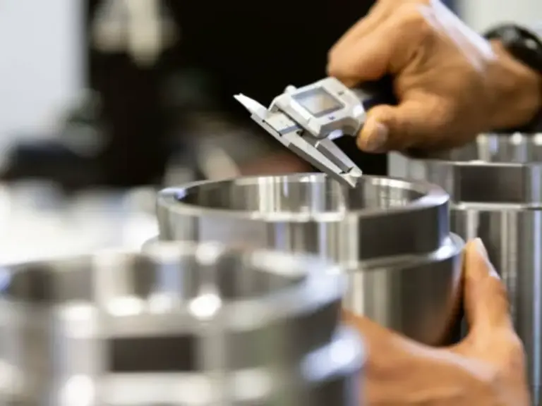
Why Casting Quality Defines Valve Performance
Although the design of the valve defines theoretical performance, the actual reliability is defined by the quality of the manufacturing. A properly designed valve made by porous casting will surely fail. This is especially the case with the valve body and valve gate that has to withstand pressure cycles and corrosive media.
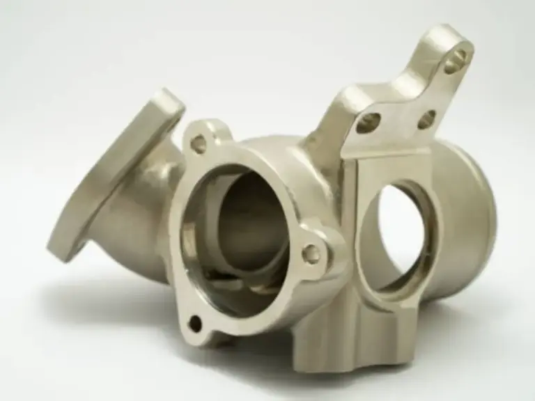
Standard sand casting is used to produce many generic valve parts and this usually leads to rough surface finishes and internal voids. Investment casting (the silica sol process in particular) is the best manufacturing process to use especially in stainless steel and alloy valves to achieve maximum performance.
The Advantage of Investment Casting (Silica Sol Process)
Internal components must be created with absolute precision. At Besser Cast, we differentiate ourselves from the competition by employing the advanced silica sol investment casting process, which offers levels of material purity and geometric precision that sand casting simply cannot match.
- Meticulous Chemical Control: We perform pre-furnace batching and control every melt with a high-precision German SPECTRO spectrometer. Whether we are casting simple stainless steels or more than 200 grades of complex alloys, we ensure the exact metallurgical signature meets whichever global standard is stipulated (ASTM, DIN, JIS).
- Geometric Precision & Thin Wall Capability: Thanks to our vacuum casting technologies, we are able to achieve wall thicknesses of 0.5mm and better surface finishes than our competitors. Because of this precision, turbulence is reduced in the flow path, and the need for secondary machining is eliminated (saving weight and increasing strength).
- Certified Reliability: Quality is systemic. Our manufacturing is backed by advanced simulation software and is certified to PED and AD2000, which are fundamental to the safety of pressure equipment. Each and every lot provides full traceability of their dimensions and chemistry.
Common Part Failures and Maintenance Tips
Even the right valve should be monitored. Knowledge of failure modes assists in scheduling routine maintenance.
- Stem Leakage: This is the most widespread problem, and it is normally brought about by the slackening of the stem packing. The seal can be regained by tightening the gland flange nuts in a uniform manner. If the packing is hard and brittle as a result of high temperatures, it should be changed.
- Seat Leakage (Passing): In case the valve fails to close fully, debris can be trapped in the valve seat, or the sealing material can be scored. In gate valves, it is sometimes possible to clear debris by flushing the line with the valve partially open. Constant leakage necessitates lapping of the seats.
- Stuck Valve: A valve that is not functioning can have a damaged stem nut or be thermally bound. Flexible wedge designs minimize the binding risk in temperature applications.
Conclusion
The gate valve is a misleadingly simple mechanism. It is dependent on the exact contact of the valve stem, gate, and seat in a strong valve body. The choice of the right type of valve and different materials is basic, whether it is fluid flow at extreme temperatures or work with corrosive chemicals.
But specification sheets do not give the entire story. Valve safety is based on the integrity of the casting process. With a focus on accuracy in manufacturing techniques, including the silica sol investment casting process provided by Bessercast, engineers and procurement heads will be able to guarantee that their industrial valves provide accurate control, tight seals, and long-term performance. Quality manufacturing is directly related to operational efficiency and safety, whether it is the chemical stability of the alloy or the dimensional accuracy of the flow path.