Types of Pump Impellers: A Complete Guide to Design, Selection, and Manufacturing
The impeller is the heart of a centrifugal pump — the rotating component that converts mechanical energy from the motor into fluid kinetic energy. Choosing the wrong impeller type doesn’t just reduce efficiency; it can lead to chronic clogging, premature wear, cavitation damage, and unplanned downtime that costs far more than the pump itself.
Most guides stop at “open vs closed.” What they leave out is the connection between impeller design and how it’s made — and that connection is where real-world efficiency is won or lost. The casting process behind an impeller directly shapes the performance you get in the field.
The Three Core Impeller Designs — Open, Semi-Open, and Closed
The single most important variable in impeller selection is simple: what’s in your fluid? The presence or absence of shrouds — the disc-like walls that enclose the vanes — determines how well an impeller handles solids versus how efficiently it moves clean liquid. Every impeller design is a trade-off along this spectrum.
Here is the landscape at a glance:
| Type | Shrouds | Efficiency Range | Best For | Avoid When |
|---|---|---|---|---|
| Open | None | 50–60% | Slurries, large solids, sewage | High pressure, clean fluids |
| Semi-Open | Back shroud only | 50–70% | Light slurries, pulp, petrochemical | Heavy abrasives, maximum efficiency |
| Closed | Front + back | 70–90% | Clean water, hydrocarbons, HVAC | Solids > 0.5 mm, fibrous materials |
Open Impeller — Maximum Solids Handling at the Cost of Efficiency
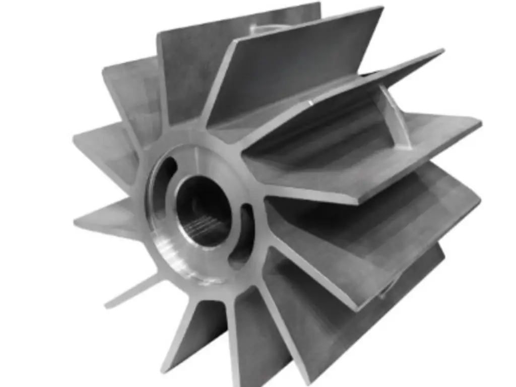
An open impeller consists of vanes attached directly to a central hub, with no shrouds on either side. Because the vanes are fully exposed, solids pass through without obstruction — making this the go-to design when clog resistance is non-negotiable.
The trade-off is efficiency. Without shrouds to constrain the flow path, fluid leaks back between the vane tips and the casing, wasting energy. Open impellers typically operate in the 50–60% efficiency range. They also require higher Net Positive Suction Head (NPSH) because the unshrouded eye creates more turbulence at the inlet.
Where they shine: mine dewatering, dredging, raw sewage, paper pulp, and any service where the fluid contains large solids or abrasive particles. Maintenance is straightforward — the impeller can be inspected and cleaned without disassembling the pump casing, and axial shimming can compensate for wear over time.
A practical note on wear management: open impellers in abrasive service are often cast in high-chrome white iron (HRC 55–65) or fitted with replaceable rubber liners. The clearance between vane tips and the casing volute — typically 0.3–0.8 mm — is the critical dimension. Once wear opens this gap beyond roughly 1.5 mm, efficiency drops sharply and the impeller should be reshimmed or replaced.
Semi-Open Impeller — The Balanced Compromise
The semi-open impeller anchors the vanes to a single back shroud while leaving the front face exposed. This hybrid design borrows structural strength from the back shroud while retaining some solids-handling capability on the open side.
Efficiency runs between 50% and 70%, placing it squarely between open and closed designs. A key engineering feature is the pump-out vanes on the back shroud — small radial ribs that reduce pressure at the stuffing box and prevent solids from packing behind the impeller. These also allow axial adjustment to maintain the critical front clearance (typically 0.3–0.5 mm during operation).
Semi-open impellers are the right call for process fluids carrying small amounts of suspended solids: chemical intermediates, paper stock, light slurries, and petrochemical streams where a closed impeller would clog but an open impeller would sacrifice too much efficiency.
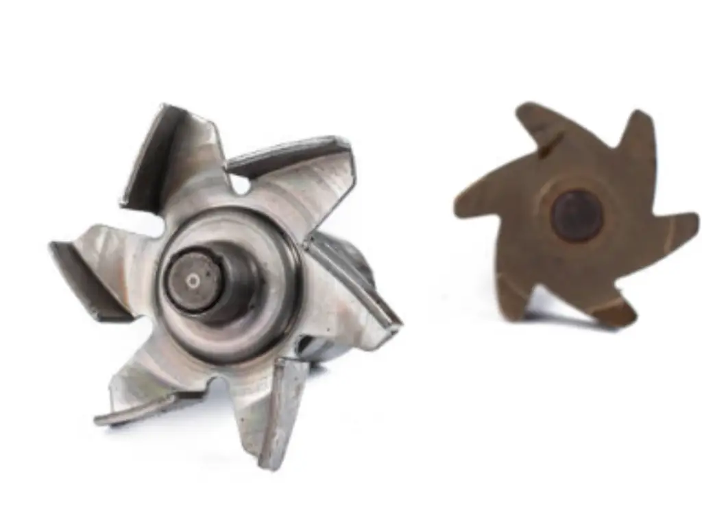
Closed Impeller — Maximum Efficiency for Clean Fluids
A closed impeller sandwiches the vanes between a front and back shroud, creating sealed internal passageways that guide fluid with minimal leakage. This is the industrial default for clean-liquid service — and for good reason: efficiency runs from 70% to 90%, the highest of any centrifugal impeller design.
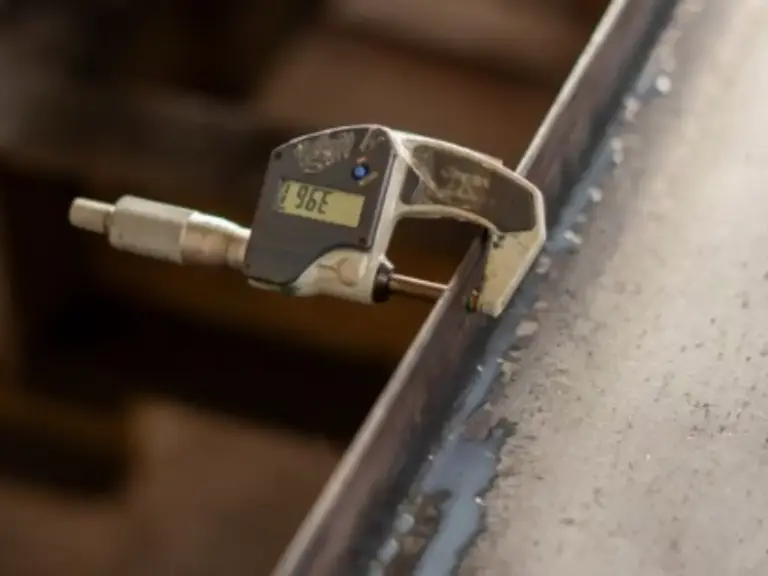
The precision of the internal flow channels is what makes or breaks a closed impeller’s performance. Castings produced to CT4–CT6 tolerance (per ISO 8062) ensure the as-built geometry matches the hydraulic design. A deviation of just 0.5 mm in channel width can shave 2–3 percentage points off efficiency — a gap that compounds into significant energy cost over a pump’s 15–20 year service life.
Closed impellers rely on wear rings — sacrificial clearance seals at the impeller eye — to control internal recirculation. In API 610-compliant pumps, the diametral wear ring clearance is held to 0.25–0.50 mm. When wear rings erode beyond tolerance, efficiency drops and vibration increases. Wear rings are replaceable, and the impeller itself can last decades in clean-fluid service.
Typical applications include HVAC circulators, boiler feed pumps, hydrocarbon transfer, and municipal water supply — any service where the fluid is clean, low-viscosity, and free of solids larger than roughly 0.5 mm.
Flow Direction — Radial, Axial, and Mixed Flow
Beyond shroud configuration, impellers are classified by the direction they discharge fluid. This second dimension — governed by the impeller’s specific speed (Nₛ) — determines whether your pump delivers high pressure at modest flow, massive flow at low pressure, or something in between. The geometry follows the physics.
| Impeller Type | Flow Pattern | Specific Speed (Nₛ)* | Head vs Flow | Typical Application |
|---|---|---|---|---|
| Radial Flow | 90° to shaft axis | 500–4,000 | High head, low-to-medium flow | Boiler feed, high-pressure cleaning, multistage pumps |
| Mixed Flow | Conical (45°–60°) | 4,000–10,000 | Medium head, medium-to-high flow | Cooling water circulation, irrigation, water distribution |
| Axial Flow | Parallel to shaft axis | 10,000–16,000 | Low head (2–20 m), very high flow (up to 40,000+ m³/h) | Flood control, condenser cooling, tank recirculation |
*US customary units: Nₛ = N√Q / H^(3/4), where N = RPM, Q = GPM, H = ft per stage at BEP.
As specific speed increases, the impeller transitions from a narrow, large-diameter radial wheel to a broad, propeller-like axial design. Mixed flow sits between them — a conical discharge pattern suited to medium-head applications.
For most industrial pump users, radial flow closed impellers cover the vast majority of applications. Axial and mixed-flow designs enter the picture only when flow rates exceed what a radial impeller can practically deliver in a single stage.
Specialty Impellers for Solids, Slurries, and Wastewater
When the fluid contains more than trace solids — think raw sewage, industrial sludge, or fibrous debris — the standard three-type classification isn’t enough. Specialty impellers trade efficiency for passage capability, and the selection logic shifts: first determine the maximum solid size your pump must pass, then choose the impeller that clears it with the least efficiency penalty.
Vortex (Recessed) Impeller — When Clog-Free Operation Is Non-Negotiable
A vortex impeller sits recessed in the pump casing’s back chamber, creating a rotating vortex that moves fluid and solids through the pump without the solids contacting the vanes directly. The hydraulic coupling transmits energy without mechanical displacement — the vanes never touch what they’re pumping.
The result is the closest thing to a clog-proof impeller. Solids up to 100 mm and long-fibre materials like rags and wet wipes pass through reliably. The cost: efficiency tops out at 59%, according to KSB’s published performance data for their F-max vortex design (KSB SE & Co. KGaA, 2025). Energy consumption runs roughly 30–40% higher than a closed impeller moving the same flow.
Use a vortex impeller when downtime from clogging costs more than the energy penalty — raw sewage intake, combined sewer overflows, and industrial wastewater with unpredictable solids loads are the classic cases. The efficiency ceiling also means vortex pumps should be right-sized carefully: oversizing compounds the energy waste.
Channel Impeller — High Efficiency Solids Handling
A channel impeller uses a closed design with 2–3 oversized, smooth-walled passages instead of multiple narrow vanes. The large channels allow solids through while the shrouded construction preserves hydraulic efficiency.
The performance gap is striking: closed multi-channel impellers reach 86% best efficiency, nearly matching clean-liquid closed impellers while passing solids up to approximately 80 mm (KSB SE & Co. KGaA, 2025). Open-channel variants (radial multi-vane) achieve 84% and handle up to 8% dry solids content.
The trade-off: channel impellers need pre-screened or mechanically treated wastewater. Long fibres can still wrap around the vanes, and gas content above roughly 5% causes performance instability. For activated sludge, stormwater, and industrial effluent with predictable solids characteristics, the channel impeller is often the optimal balance of efficiency and reliability.
Cutter and Grinder Impellers — Active Solids Reduction
Where vortex and channel impellers passively pass solids through, cutter and grinder impellers actively destroy them before pumping.
A cutter impeller integrates a sharp-edged cutting mechanism at the impeller inlet that shears fibrous materials — wipes, rags, denim — into fragments small enough to pass through the discharge. Efficiency is low (roughly 42%), but the alternative in small-diameter discharge lines (DN 32–65) is frequent blockage. Cutter pumps are standard in pressure sewer systems where solids must travel long distances through small pipes.
A grinder impeller goes further, macerating solids against a stationary cutting ring until they pass through a strainer plate — typically 6–10 mm openings. Grinder pumps are specified when downstream equipment (screens, filters, membranes) has tight solids-passage limits, or when the discharge line diameter is simply too small for anything larger.
How Impeller Design Shapes the Manufacturing Process
This is the dimension most articles skip — and it matters. The impeller type you select doesn’t just determine how the pump performs; it dictates how the impeller must be made. Understanding this connection helps you evaluate suppliers, compare quotes intelligently, and spot quality risks before they become field failures.
Here is how the mapping works:
| Impeller Type | Typical Process | Key Quality Driver |
|---|---|---|
| Closed (small-to-medium, ≤ 50 kg) | Silica sol investment casting | Internal channel precision, surface finish |
| Open / Semi-open (any size) | Investment casting or sand casting | Wear resistance, dimensional stability |
| Large (diameter > 500 mm) | Sand casting + CNC finishing | NDT coverage, balance grade |
Investment Casting — Precision Manufacturing for Complex Impeller Geometries
Closed impellers present a manufacturing challenge: the internal flow channels between the shrouds are inaccessible to machine tools. The only way to create these passages is to form them during casting — and the only process with the geometric capability is silica sol investment casting (also called lost wax casting).
The process starts with a wax pattern — an exact replica of the finished impeller, including the internal channels. This pattern is dipped repeatedly in a ceramic slurry to build up a shell 6–7 layers thick, with each layer dried for 4–6 hours. A foundry with automated shell-making lines can complete the full shell buildup in about 36 hours — roughly five times faster than manual shell-building, and with far better consistency.
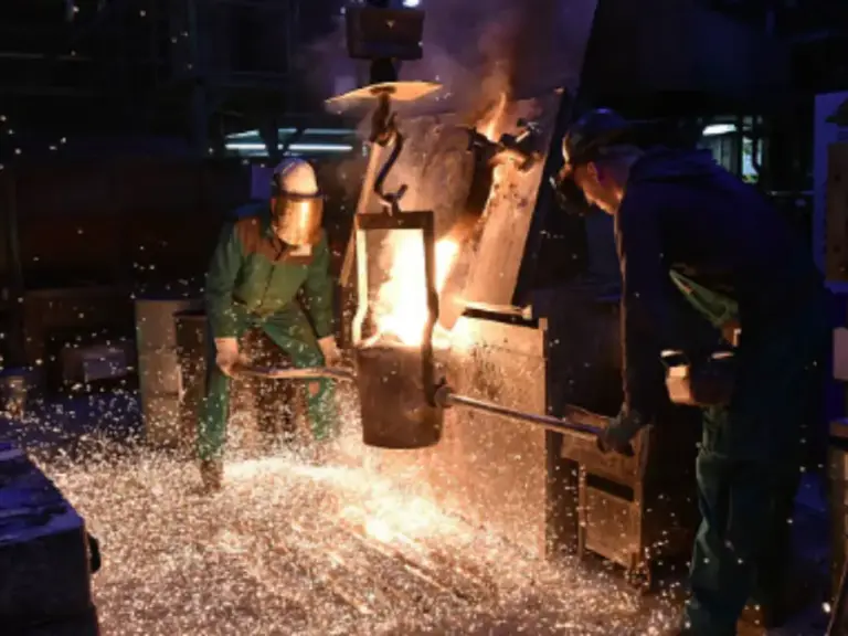
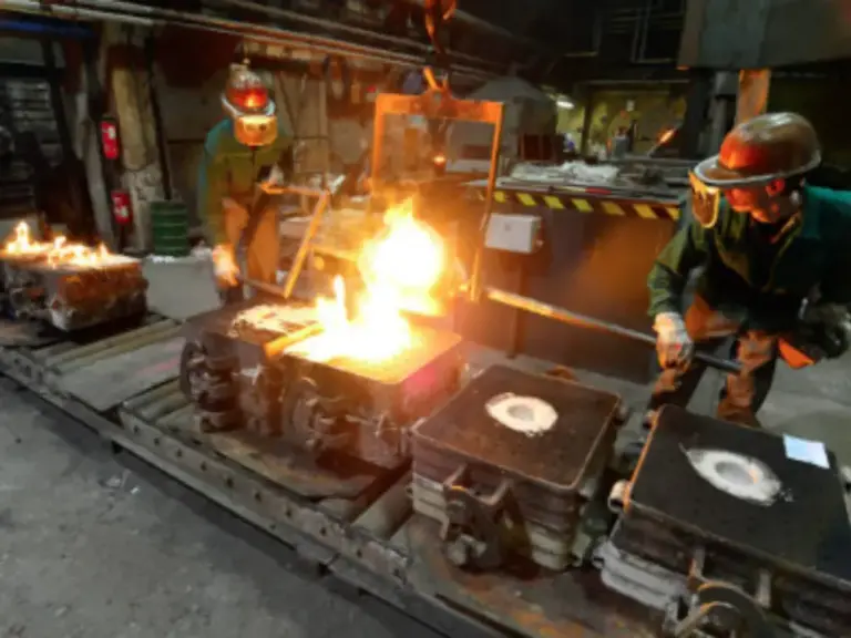
After dewaxing and firing, molten metal is poured into the ceramic shell. Once solidified, the shell is broken away, revealing a near-net-shape impeller that needs only minimal finish machining on the bore, faces, and balance surfaces.
The precision is what matters for pump performance. Investment casting routinely achieves CT4–CT6 dimensional tolerance (ISO 8062) and Ra 3.2 μm surface finish on the flow passages — meaning the as-cast geometry closely matches the hydraulic designer’s CAD model. For a closed impeller with 5–7 vanes and complex 3D curvature, this near-net precision directly translates to on-spec efficiency at the duty point.
Foundries that can pair this precision with a broad alloy range — stainless steels (304, 316, duplex), nickel-based alloys (Hastelloy, Inconel), and tool steels — give pump OEMs a single-source solution across their entire impeller portfolio. When evaluating a casting supplier, ask about their shell-making automation, tolerance capability, and alloy coverage. These three factors determine both lead time and quality consistency.
Sand Casting and Alternative Methods — When Size and Economy Dictate the Process
For large impellers — think 500 mm diameter and above — investment casting becomes impractical. The wax patterns become unwieldy, the ceramic shells require enormous handling equipment, and the cost curve bends sharply upward. Beyond the 50–100 kg range, sand casting takes over as the economic choice.
The trade-off is precision. Sand casting typically achieves CT8–CT10 tolerances — two to four grades looser than investment casting. Surface finish is rougher, and more stock must be left for finish machining. But for large open or semi-open impellers with simpler geometries, the cost savings outweigh the extra machining time.
Post-casting, large impellers require more extensive CNC work: bore machining, face turning, vane tip profiling, and dynamic balancing. The balance grade target is typically G6.3 or G2.5 (ISO 1940), achieved by adding or removing weight at specific locations.
For rapid prototyping or highly complex cooling channels not achievable by casting, 3D printing (additive manufacturing) is an emerging option — though currently limited to small volumes and specialty alloys.
Matching Impeller Material to Fluid Service
You’ve selected the impeller type. Now you need the material. The wrong alloy choice can destroy an otherwise perfectly designed pump in weeks.
The three variables that drive material selection are fluid chemistry (corrosion), temperature (mechanical properties at operating temperature), and abrasiveness (erosion resistance). The table below maps common fluid services to standard material choices.
| Material | Best For | Avoid When | Typical Impeller Type |
|---|---|---|---|
| Cast Iron (Grey/Ductile) | Clean cold water, neutral pH | Corrosive fluids, seawater | Closed (large), Open |
| Bronze | Seawater, mildly corrosive | High-velocity sand (erosion) | Closed (marine pumps) |
| 304/316 Stainless Steel | Food-grade, mild chemicals, hot water | High chloride (Cl⁻ > 200 ppm → 316L or duplex) | Closed, Semi-open |
| Duplex Stainless (2205) | Seawater, chlorides > 200 ppm, acids | Budget-sensitive (2–3× 316 cost) | Closed (critical service) |
| High-Chrome White Iron | Abrasive slurries, mine tailings | Impact loads (brittle) | Open, Semi-open |
| Nickel-Based (Hastelloy, Inconel) | Strong acids, > 800°C service | Standard applications (overkill) | Closed (specialty) |
A note on chlorides: 316L stainless is adequate for chloride concentrations up to roughly 200 ppm at ambient temperature, but this threshold drops sharply as temperature rises. For seawater or brackish water applications, duplex stainless steel (2205) tolerates chloride levels above 1,000 ppm and offers roughly double the yield strength of 316L — allowing thinner, lighter impeller designs at the same pressure rating.
For extreme environments — concentrated acids, cryogenic temperatures, or high-temperature oxidizing atmospheres — nickel-based superalloys become necessary. Foundries with experience across 200+ alloy grades can guide material selection beyond what a standard catalog covers.
If you’re sourcing pump impellers and need a manufacturing partner with precision investment casting capability — including CT4–CT6 tolerances, Ra 3.2 surface finish on internal flow passages, and metallurgical coverage across 200+ alloys — BesserCast (www.bessercast.com) is a specialized precision investment casting foundry with over 20 years of experience in pump component casting.
References
- KSB SE & Co. KGaA. “Waste water applications: Selecting pump impellers.” 2025. https://www.ksb.com/en-gb/solutions/waste-water-technology/selecting-pump-impellers
- ISO 8062-3:2007. “Geometrical product specifications (GPS) — Dimensional and geometrical tolerances for moulded parts.” International Organization for Standardization.
- API Standard 610. “Centrifugal Pumps for Petroleum, Petrochemical, and Natural Gas Industries.” American Petroleum Institute.
- ISO 1940-1:2003. “Mechanical vibration — Balance quality requirements for rotors in a constant (rigid) state.” International Organization for Standardization.
- BesserCast. “Precision Investment Casting Manufacturer.” https://www.bessercast.com/
- BesserCast. “Pump Materials & Component Casting.” https://www.bessercast.com/pump-materials/
- BesserCast. “Contact.” https://www.bessercast.com/contact/