Machining Allowance in Casting: How to Specify It Right (With a Worked Example)
What Is Machining Allowance in Casting — and Why It’s Not Just “Extra Metal”
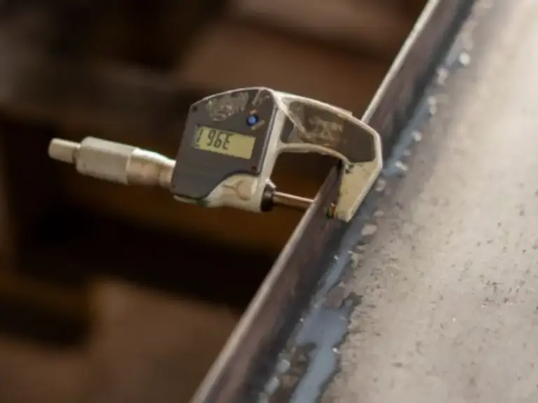
Machining allowance is the layer of material intentionally left on a casting’s surface. That material gets removed later by CNC machining to hit the final dimensions, tolerances, and surface finish on the engineering drawing.
The word “intentionally” matters. Machining allowance is not a safety margin you slap on because you’re unsure about the foundry’s capability. It is a calculated design parameter, governed by international standards, and directly tied to both part quality and production cost.
A useful analogy: think of a tailor leaving a 1.5 cm seam allowance when cutting fabric. The extra cloth isn’t waste — it’s the working space needed to sew the garment to its finished dimensions. A casting’s machining allowance does the same thing. The foundry delivers a near-net-shape part. The machine shop cuts it to final spec.
But here’s where most engineers get it wrong on their first casting project: they confuse machining allowance with machining tolerance. Tolerance defines how precisely a finished dimension must be held (±0.05 mm, for example). Allowance defines how much extra material sits on the raw casting for the machinist to work with. These are separate concepts, governed by separate sections of the same standard. Conflate them, and you get parts that either cost too much to machine or cannot be cleaned up at all.
Even investment casting — the highest-precision casting process, capable of CT4–CT6 tolerances and Ra 3.2 as-cast surface finishes — still leaves certain features needing post-casting machining. Bearing bores, threaded holes, sealing faces, and tight-tolerance assembly interfaces rarely meet final specifications in the as-cast state. The question isn’t whether you need machining allowance. It’s how much. And the answer depends on your casting process, part size, and material.
How Much Allowance Should You Specify? Standards and Process Guidelines
The international reference for machining allowance is ISO 8062-3:2023, which defines Required Machining Allowance (RMA) grades for castings across all metal alloys and processes. The standard provides lookup tables based on two variables: the casting’s largest overall dimension and the RMA grade for the casting process. No guesswork needed.
Here’s a simplified reference table for RMA Grade E — the grade typically recommended for investment castings:
| Largest Dimension (mm) | RMA — Grade E (mm) |
|---|---|
| ≤ 40 | 0.4 |
| 40 – 63 | 0.4 |
| 63 – 100 | 0.7 |
| 100 – 160 | 1.1 |
| 160 – 250 | 1.4 |
| 250 – 400 | 2.2 |
But RMA alone doesn’t tell the whole story. The actual machining allowance also depends on your casting process. Different processes produce dramatically different surface quality and dimensional consistency. That changes how much material the machine shop needs to clean up:
| Casting Process | Typical Allowance (mm) | Surface Finish (Ra, μm) | Tolerance Grade |
|---|---|---|---|
| Sand Casting (manual) | 3.0–5.0 | 12.5–25 | CT10–CT13 |
| Sand Casting (machine) | 2.0–3.0 | 6.3–12.5 | CT8–CT10 |
| Gravity Die Casting | 1.1–2.25 | 3.2–6.3 | CT7–CT9 |
| Investment Casting (Silica Sol) | 0.5–1.5 | 3.2 | CT4–CT6 |
| Pressure Die Casting | 0.375–0.75 | 1.6–3.2 | CT5–CT7 |
The takeaway is clear: investment casting needs the least machining allowance of any conventional casting process. Where a sand casting might need 4 mm of stock on a 200 mm part, an equivalent investment casting might get away with 1.4 mm. That difference compounds across every machined surface on every part in a production run.
Even within investment casting, the allowance you can specify depends on the foundry’s process control. A foundry running automated shell-making lines with consistent layer thickness holds tighter dimensional repeatability than one building shells manually. Tighter repeatability means a smaller RMA safety factor works reliably.
The Hidden Cost of Getting Machining Allowance Wrong
The Price of Over-Specifying: Machining Time, Tool Wear, and Wasted Material
Every millimeter of unnecessary machining allowance has a price tag — and the bill arrives in three places at once.
First, machining time. CNC shops charge by the hour. If your casting carries 3 mm of allowance where 1.5 mm would suffice, the roughing passes double. On a pump housing with a 60-second roughing cycle per face, an extra 1.5 mm of stock across eight machined faces adds roughly 8 minutes of cycle time per part. At $80–120/hour shop rates and a 500-piece production run, that single millimeter costs between $5,000 and $8,000.
Second, tool wear. Carbide inserts cutting through extra stock wear faster, especially on abrasive materials like cast stainless steel. Tooling cost per part rises. More frequent insert changes mean more machine downtime.
Third, material efficiency. The aerospace industry tracks this with the buy-to-fly (BTF) ratio: how many kilograms of raw material enter the supply chain for every kilogram of finished part. Machining a titanium structural component from solid billet can hit a BTF of 37:1. Sand casting plus machining improves that to roughly 3–5:1. Near-net-shape investment casting plus finish machining drives it down to 1.5–2:1 (MX3D, 2024). That improvement in material utilization reduces raw material cost, shortens lead times, and shrinks the carbon footprint of every part.

The Risk of Under-Specifying: When “Just Enough” Becomes “Not Enough”
After seeing the cost of over-specifying, the instinct is to cut allowance to the bone. Resist that instinct. Under-specifying creates a different, more expensive problem: scrap.
The most common failure mode is residual casting skin. Carbon steel castings develop a decarburized surface layer roughly 0.3–0.5 mm deep during cooling. If your machining allowance is thinner than that layer plus the casting’s surface imperfections, the cutting tool never reaches sound metal. Waviness and form deviation add real depth beyond the Ra 3.2 roughness number. What’s left is a surface peppered with micro-scale oxides and depleted carbon — a stress concentrator that will fail in service.
A second failure mode comes from subsurface defects. Investment castings, while far cleaner than sand castings, can still contain near-surface inclusions or micro-porosity within the first 0.2–0.5 mm of the as-cast surface. If your allowance is thinner than the typical inclusion depth for your material and process, these defects survive machining. They end up embedded in the finished part.
The third failure mode is datum misalignment. The casting datum — the reference surface used to fixture the raw casting for first-operation machining — often differs from the design datum used to dimension the finished part on the drawing. When these two reference frames don’t align, the positional error eats into your allowance before the first chip is cut. A 0.3 mm datum shift on a part with only 0.5 mm of allowance leaves just 0.2 mm of clean-up stock. On a casting with typical form deviation, that’s dangerously thin.
Near-Net-Shape Investment Casting: Why Less Allowance Is Possible
So how do you get low allowance without the risk? The answer lies in the process technology that makes investment casting capable of near-net-shape production.
The shell sets the surface. Investment casting uses a silica sol binder to build a ceramic shell around a wax pattern. Each of the 6–7 shell layers is dipped and stuccoed under controlled conditions. On a fully automated shell line, these layers build up with consistent thickness and density across the entire surface of every pattern. The result is an internal cavity smooth enough to deliver Ra 3.2 as-cast. Manual shell building, by contrast, introduces operator-to-operator and day-to-day variation that forces engineers to pad the allowance “just in case.”
Consistency enables tighter safety factors. When every shell in a production batch has the same layer structure and permeability, the dimensional variation from casting to casting shrinks. This lets a foundry hold CT4–CT6 tolerances on critical dimensions. These tolerances approach those of European foundries. They are tight enough that the RMA table’s standard values become truly achievable, not aspirational.
Simulation replaces guesswork. Modern foundries use casting simulation software to predict solidification shrinkage, distortion, and residual stress before cutting a single mold. When simulation shows exactly where and how much a part will distort, the allowance can be locally optimized. Stock gets added only where needed, rather than applied as a uniform blanket across every surface (Mrozek et al., TU Delft, 2012).
Together, these three factors explain why a well-equipped investment casting foundry can deliver parts that need half the machining allowance of a conventional sand casting. And they can do it without increasing scrap risk.
How to Calculate Machining Allowance for Your Part: A Worked Example
The calculation itself is straightforward. The setup, however, trips up first-timers. You need two numbers from ISO 8062-3:2023 (ISO, 2023):
- RMA (Required Machining Allowance) — Looked up from the standard’s table based on your casting’s largest overall dimension (NOT the dimension of the feature being machined) and the RMA grade for your process. This is the single most common lookup error.
- CT (Casting Tolerance) — Looked up from a separate table based on the nominal dimension range and the tolerance grade your foundry guarantees (e.g., CT5 for investment casting).
The formula then depends on which type of surface you’re calculating for:
- External surface (e.g., turning an OD):
R = F + 2 × (RMA + CT/4) - Internal surface (e.g., boring an ID):
R = F − 2 × (RMA + CT/4) - End face (e.g., milling a flange face):
R = F + (RMA + CT/2)
Where R is the casting dimension and F is the finished part dimension.
Why the CT/4 and CT/2 terms? Casting tolerance consumes part of your allowance. On an external surface, half the tolerance band could push the as-cast surface outward, so you add CT/4 per side. On an end face, the full tolerance band could shift the face position, so you add CT/2.
Worked Example: Calculating Allowance for a Pump Impeller
Let’s walk through a real calculation. Consider a 316 stainless steel pump impeller produced by silica sol investment casting:
Part specifications:
- Maximum outer diameter (finished): 180 mm
- Critical machined features: shaft bore (internal surface, finished Ø40 mm), seal face (end face), OD (external surface)
- Casting tolerance grade: CT5
Step 1 — Find RMA.
The part’s largest overall dimension is 180 mm, which falls in the 160–250 mm range. For RMA Grade E (investment casting), the table gives: RMA = 1.4 mm.
Step 2 — Find CT.
For a nominal dimension of 180 mm under CT5: CT = 1.0 mm (from ISO 8062-3 tolerance tables).
Step 3 — Calculate casting dimensions.
For the OD (external surface, finished Ø180 mm):
R = F + 2 × (RMA + CT/4)R = 180 + 2 × (1.4 + 1.0/4)R = 180 + 2 × (1.4 + 0.25)R = 180 + 2 × 1.65R = 180 + 3.3R = 183.3 mm → specify 183.5 mmFor the shaft bore (internal surface, finished Ø40 mm):
R = F − 2 × (RMA + CT/4)R = 40 − 2 × (1.4 + 0.25)R = 40 − 3.3R = 36.7 mm → specify 36.5 mmFor the seal face (end face position):
R = F + (RMA + CT/2)R = F + (1.4 + 1.0/2)R = F + 1.9 mmAdd 1.9 mm to the finished face position on the casting drawing.
Step 4 — Document on your drawing.
On the casting drawing, the OD dimension reads Ø183.5 ±0.5 (CT5) with a machining symbol and the note “STOCK +1.65/SIDE.” On the machining drawing, the same feature reads Ø180 ±0.05 (finished).
Note: the ~2.5% solidification shrinkage of 316 stainless steel is compensated in the wax pattern tooling, not in these calculations. The pattern is made slightly larger than the casting drawing specifies. This is the foundry’s responsibility and does not affect your allowance numbers.
Common Mistakes in Allowance Calculation (and How to Avoid Them)
❌ Mistake #1: Using the machined feature’s dimension to look up RMA.
If the 180 mm OD has a 25 mm bearing bore, don’t look up RMA in the ≤40 mm row. The RMA lookup always uses the part’s maximum overall dimension (180 mm → 1.4 mm). The entire casting’s dimensional behavior determines how much stock is needed, not just one feature’s. ✅ Always use the largest overall dimension of the entire casting.
❌ Mistake #2: Applying the same formula to all surfaces.
External surfaces add allowance. Internal surfaces subtract it. End faces add half the amount. Applying the external formula to a bore gives a casting dimension that’s too large. The bore gets bigger, not smaller, and there’s nothing left to machine. ✅ Identify surface type before selecting the formula variant.
❌ Mistake #3: Ignoring datum mismatch.
The casting datum used for first-operation fixturing often differs from the design datum used to dimension the finished feature. Add 0.3–0.5 mm of extra allowance to compensate for the accumulated positioning error between the two reference frames. ✅ Confirm datum strategy with both foundry and machine shop before locking allowance values.
What to Ask Your Foundry About Machining Allowance
Knowing the standard and running the calculation puts you ahead of most engineers sending out their first casting RFQ. But the real test comes when you talk to the foundry. Here are five questions that separate a supplier who can deliver from one who’s guessing:
1. “What tolerance grade can you reliably hold on my part size?”
Every foundry claims CT4–CT6 for investment casting. Ask for dimensional capability data on parts similar in size and geometry to yours. The answer should reference actual CMM inspection reports, not a brochure number or a sales promise.
2. “How do you build your ceramic shells?”
The difference between a manually dipped shell and one built on an automated line is the difference between a consistent 0.5 mm allowance working every time and needing a 1.5 mm safety factor “just in case.” Automated shell lines produce shells with uniform layer thickness across the entire surface of every pattern. That uniformity is what lets you specify minimal allowance with confidence.
3. “What’s your first-sample pass rate?”
A foundry that achieves above 90% first-article approval has the process control to back up its tolerance claims. A lower rate isn’t necessarily disqualifying, but it means you should budget extra allowance. Or expect more iteration.
4. “Do you use casting simulation software?”
Simulation (like MAGMASOFT) predicts where a casting will distort during solidification. Foundries that simulate can apply allowance locally, adding stock only where distortion is predicted rather than padding every surface uniformly. The difference in practice: an optimized 1.4 mm allowance versus a blanket 3 mm.
5. “How do you verify actual allowance distribution on first articles?”
The right answer involves CMM inspection or 3D scanning of the raw casting, overlaid against the CAD nominal, with a report showing stock distribution across all machined surfaces. If the answer is “we measure a few points with calipers,” look deeper.
When you ask these questions, the answers tell you what’s possible. A foundry running two fully automated silica sol shell lines, holding CT4–CT6 tolerances, and backing its work with a 95% first-sample pass rate and casting simulation can deliver parts where the ISO 8062 RMA table values are not a theoretical target. They are a production reality. For parts like the pump impeller in our worked example, that means specifying 1.4 mm of allowance — and getting exactly that, batch after batch.