The Engineer’s Guide to Investment Casting Tolerances — Beyond the ISO 8062 Table
If you design or source metal parts, you have probably stared at a casting tolerance chart and asked yourself three questions: Can my part really hold ±0.18mm at 50mm? Will the batch be consistent? And why did the last supplier’s CT5 castings measure more like CT7?
This guide answers all three. We cover the ISO 8062 CT grade system, what investment casting delivers across linear, geometric, and surface finish dimensions, the root causes behind tolerance variation that most supplier pages skip, and a practical framework for specifying tolerances without driving up cost.
What Are Investment Casting Tolerances — CT Grades and ISO 8062
A casting tolerance grade (CT) expresses how precisely a cast part matches its nominal dimensions. The international standard is ISO 8062-3 — Dimensional and geometrical tolerances for moulded parts — Part 3: General dimensional and geometrical tolerances and machining allowances for castings (ISO, 2007; updated 2023). China uses the equivalent GB/T 6414. Germany historically references VDG P690, where grade D2 roughly equals CT5.
The CT scale runs from CT1 (tightest) to CT16 (loosest). For silica sol investment casting — the most precise casting process available for steel and stainless alloys — the production range is CT4 to CT6.
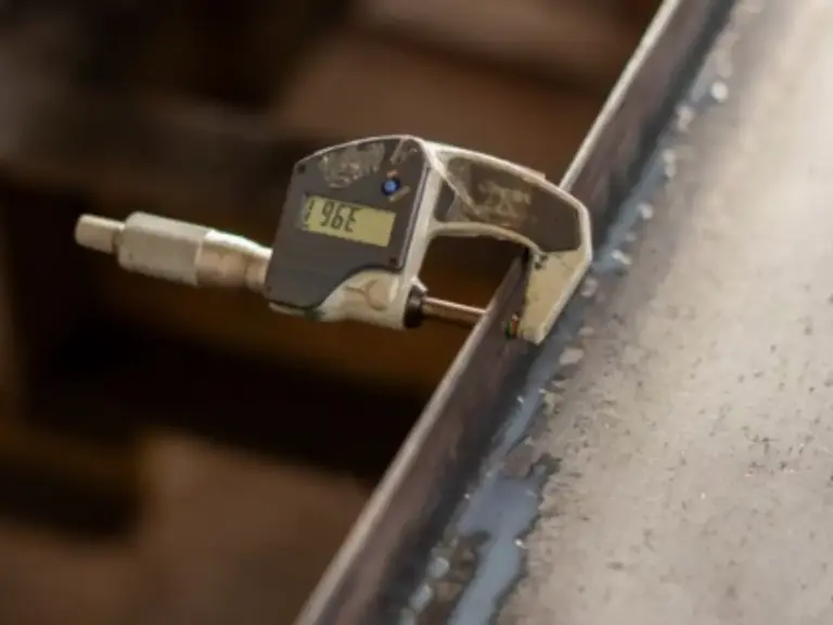
Important: The CT value is the total tolerance band. For bilateral ± tolerances on a drawing, divide by two. A dimension at CT6 with a 0.52mm total band means ±0.26mm — not ±0.52mm. This is the single most common drawing mistake engineers make when first working with the standard.
ISO 8062 Linear Tolerance Table — CT4 to CT8
| Nominal Dimension (mm) | CT4 (±) | CT5 (±) | CT6 (±) | CT7 (±) | CT8 (±) |
|---|---|---|---|---|---|
| 0–10 | ±0.13 | ±0.18 | ±0.26 | ±0.37 | ±0.50 |
| 10–16 | ±0.14 | ±0.19 | ±0.27 | ±0.39 | ±0.55 |
| 16–25 | ±0.15 | ±0.21 | ±0.29 | ±0.41 | ±0.60 |
| 25–40 | ±0.16 | ±0.23 | ±0.32 | ±0.45 | ±0.65 |
| 40–63 | ±0.18 | ±0.25 | ±0.35 | ±0.50 | ±0.70 |
| 63–100 | ±0.20 | ±0.28 | ±0.39 | ±0.55 | ±0.80 |
| 100–160 | ±0.22 | ±0.31 | ±0.44 | ±0.60 | ±0.90 |
| 160–250 | ±0.25 | ±0.35 | ±0.50 | ±0.70 | ±1.00 |
| 250–400 | ±0.28 | ±0.39 | ±0.55 | ±0.80 | ±1.10 |
To make this concrete: a 50mm feature at CT4 is ±0.18mm. At CT5 it is ±0.25mm. At CT6 it is ±0.35mm. At CT8 — typical for water glass investment casting — it is ±0.70mm, four times looser than CT4.
What Investment Casting Can Achieve — Linear, Geometric, and Surface Benchmarks
The CT grade table gives you numbers. But three dimensions of tolerance quality interact with each other, and you cannot push all three to their limits at once. Here is what each dimension delivers in production.
Linear Tolerance — What CT4 to CT6 Means in Real Numbers
A widely used rule of thumb is ±0.005 inches per inch (±0.13mm per 25mm), or roughly ±0.5% of the nominal dimension for standard investment casting. The numbers break down by size range:
- Small parts (≤25mm): CT4 is achievable — ±0.13 to ±0.15mm. Dimensions in this range are dominated by wax pattern accuracy, which is highly controllable.
- Medium parts (25–100mm): CT5 is the production sweet spot — ±0.23 to ±0.39mm. Most foundries optimize their process here, and scrap rates stay manageable.
- Large parts (100–400mm): CT6 is the realistic target — ±0.44 to ±0.55mm. Beyond 250mm, tolerance bands grow faster than linear scaling would predict. Wax and shell thermal deformation become harder to control across larger surfaces.
Premium tolerance caveat: You can tighten key dimensions by one grade — CT4 on a 100mm feature (±0.22mm) is possible — but expect higher cost and a higher scrap rate. Reserve premium tolerances for the 3–5 dimensions that drive function.
Geometric Tolerance — Flatness, Concentricity, and What Is Realistic As-Cast
Investment casting is a near-net-shape process, not a net-shape one. Geometric tolerances as-cast follow these empirical guidelines:
| GD&T Characteristic | As-Cast Guideline |
|---|---|
| Flatness | 0.005″ per inch (0.13mm / 25mm). Surfaces over 4 inches across need machining allowance. |
| Straightness | ±0.005″ per inch. Long, unsupported sections may require straightening. |
| Roundness | ~80% of the linear tolerance band for that size. Casting is naturally good at roundness. |
| Concentricity | 0.005″ per inch of separation between diameters. |
| True Position | ±0.5–1.5mm as-cast. This is casting’s biggest weakness — locate precision features with machined datums. |
The golden rule: bearing seats, sealing faces, threaded holes, and datums must be machined. Mark them [M] on the drawing and add 1.5–2mm of stock per face. A pump body with a ±1mm as-cast bearing bore position is fine — the machined bore, referenced from a machined datum, will hit ±0.05mm.
Surface Finish — What Ra Values Investment Casting Delivers
Silica sol investment casting delivers Ra 3.2–6.3μm as-cast for most alloys. But alloy choice matters more than many designers expect:
| Alloy | As-Cast Ra (Typical) |
|---|---|
| 304/316L Stainless | 1.6–3.2μm — best as-cast finish |
| Duplex 2205 | 2.4–4.0μm — dual-phase structure produces slightly rougher surface |
| Carbon / Low-Alloy Steel | 3.2–6.3μm |
| Nickel Superalloys (Inconel, Hastelloy) | 3.2–6.3μm — vacuum casting helps metallurgy but not surface finish |
Any requirement below Ra 1.6μm means post-processing — electropolishing, vibratory finishing, or machining. A food-grade valve needing Ra 0.8μm on its flow path must budget for 0.5mm of electropolish stock. The casting alone will not get there.
Why Casting Tolerances Vary — The Root Causes Behind the CT Grade Table
This section covers what nearly every foundry’s tolerance page leaves out: the physical reasons your CT5 part sometimes measures CT7. Research by Singh, Kumar & Mishra (2010) in the International Journal of Manufacturing Technology and Management showed that wax injection parameters alone can shift a pattern’s dimensions by 0.5–1.0% before metal is ever poured (Inderscience). Understanding this chain is what separates a reliable specification from wishful thinking.
Wax Pattern Shrinkage — The Upstream Variable Most Buyers Never See
The investment casting dimensional chain starts with wax. A wax pattern is injected into a metal die, cooled, removed, and assembled onto a “tree.” Every step introduces dimensional change.
Medium-temperature investment casting wax has a linear shrinkage of 0.5–1.0% from injection temperature to room temperature. That sounds small — but on an 80mm feature, 0.8% shrinkage means the wax pattern is already 0.64mm smaller than the die cavity before any metal is poured. The foundry compensates by designing the die larger than the final part. The compensation ratio must match actual production conditions, not just the theoretical number.
The four injection parameters that control shrinkage:
- Wax temperature: Every 10°C increase adds 0.1–0.2% more shrinkage. Above 60°C, surface depression defects also increase.
- Die temperature: Every 10°C increase reduces shrinkage by 0.1–0.15%. A smaller gap between wax and die temperature produces more uniform cooling — and more predictable final dimensions.
- Holding time: 40–60 seconds for sections over 3mm. Insufficient hold time leaves the pattern under-packed, producing surface sinks and undersized dimensions.
- Storage conditions: Wax patterns need 23±2°C and 65±5% RH for at least 24 hours before assembly. Patterns that go straight from injection to the shell room are still dimensionally drifting.
A practical example: an 80mm dimension specified at ±0.25mm (≈CT5). With wax at 60°C and die preheated to 50°C (a 10°C gap), shrinkage is ~0.8%, giving a wax pattern of 79.36mm. After shell expansion and alloy solidification, the final casting lands at 79.6–80.1mm — comfortably within CT5. But if the die was not preheated (ambient 20°C, a 40°C gap), shrinkage jumps to ~1.1%. The wax pattern measures 79.12mm, and the final casting likely falls below the lower tolerance limit.
Shell, Alloy, and Cooling — The Downstream Variables
Once the wax pattern enters the ceramic shell room, a new set of variables takes over.
Shell construction: Silica sol shells require 6–7 dip-coat-stucco cycles. Each cycle needs 4–6 hours of controlled drying. Automated shell lines complete this in ~36 hours; manual lines take up to 7 days. Uneven drying between layers creates shell thickness variation, which translates directly to dimensional scatter in the casting. An automated line does not just improve throughput — it improves dimensional consistency.

Alloy solidification shrinkage: Different alloys shrink differently during freezing and cooling. A foundry that claims “CT4–CT6” without specifying the alloy is leaving out half the story:
| Alloy | Linear Solidification Shrinkage | Achievable CT (Production) |
|---|---|---|
| Carbon / Low-Alloy Steel | 2.0–2.5% | CT4–CT5 (most predictable) |
| 304/316L Stainless | 2.5–2.8% | CT4–CT5 |
| Duplex 2205 | 2.3–3.0% (wider scatter) | CT5–CT6 |
| 17-4PH | 2.5% + aging distortion | CT5–CT6 (specify “dimensions at H900 condition”) |
| Nickel Superalloys | 2.5–3.5% | CT6 (realistic floor) |
The 17-4PH case deserves special attention. This alloy undergoes a martensitic transformation during aging that produces a secondary dimensional shift. A part that measures in-spec after solution annealing may drift out of tolerance after H900 aging. The drawing must state: “Dimensions verified at final heat-treated condition (H900).”
Investment Casting vs Other Processes — How Tolerances Compare
If you are evaluating which process can hit your tolerance requirements, here is the cross-process comparison at a 50mm nominal dimension:
| Process | Typical CT Grade | Tolerance at 50mm (±) | Surface Finish (Ra) | Steel Capable? |
|---|---|---|---|---|
| Silica Sol Investment Casting | CT4–CT6 | ±0.18–0.35mm | 1.6–3.2μm | Yes |
| Water Glass Investment Casting | CT7–CT8 | ±0.50–0.70mm | 6.3–12.5μm | Yes |
| High-Pressure Die Casting | CT4–CT7 | ±0.18–0.45mm | 1.6–3.2μm | No (Al/Zn/Mg only) |
| Shell Mold Casting | CT7–CT9 | ±0.50–1.0mm | 6.3–12.5μm | Yes |
| Green Sand Casting | CT11–CT14 | ±1.1–2.8mm | 12.5–25μm | Yes |
The bottom line: if your part is steel or stainless and needs better than ±0.5mm, silica sol investment casting is your only casting option. Die casting matches the precision but cannot handle ferrous alloys. Sand casting and water glass investment casting cost less but trade away 3–5× the tolerance band.
How to Specify Investment Casting Tolerances Without Over-Engineering
Knowing the numbers is one thing. Putting them on a drawing correctly is another — and this is where cost gets baked in unnecessarily.
The As-Cast vs Machined Decision Framework
The single most expensive drawing error in investment casting is applying CNC-level tolerances to as-cast surfaces. Every dimension on a casting drawing falls into one of three categories:
Leave as-cast (mark nothing or “CT6 unless otherwise specified”):
- External contours and cosmetic surfaces
- Non-functional fillets and radii
- Cooling fins, ribs, and stiffeners
- Flow passages and internal cavities (unless sealing)
- General wall thickness
Must machine (mark [M]):
- Bearing bores and seats
- O-ring and gasket sealing faces
- Threaded holes of any type
- Dowel pin holes and locating features
- Mating surfaces requiring flatness ≤0.05mm
- Keyways and splines
- Datum surfaces used for inspection
Negotiate with the foundry:
- Large flat surfaces (>100×100mm with flatness <0.3mm)
- Long-span dimensions (>250mm between features, ≤±0.5mm)
- Thin-wall areas (<2mm over large surfaces)
Why this matters: Every extra dimension marked [M] or called out at CT4 instead of CT6 adds machining time, inspection time, and scrap risk. A foundry will price a drawing with 5 critical dimensions very differently from one with 50.
Drawing Callout Conventions — Templates You Can Use Today
Here is a general notes block you can adapt and drop into your next casting drawing:
DIMENSIONAL TOLERANCES PER ISO 8062-3 CT6 UNLESS OTHERWISE SPECIFIED.
SURFACES MARKED [M] ARE TO BE CNC MACHINED. ALL OTHER SURFACES AS-CAST.
AS-CAST SURFACE FINISH: Ra 6.3 MAX. MACHINED SURFACES: Ra 1.6 MAX.
GATE RESIDUAL: 0.25mm MAX.
FIRST ARTICLE INSPECTION REPORT (CMM) REQUIRED.
Three common mistakes to avoid:
- ±0.05mm on an as-cast surface. Fix: either mark it [M] and add machining stock, or open it to a realistic CT grade.
- One tolerance block for everything. Fix: separate “general casting tolerance” (CT6) from “machined feature tolerance” (±0.05mm or per ISO 2768-m).
- Datums on un-machined cast surfaces. Fix: machine at least one datum plane and reference all critical GD&T from it.
Before you finalize the drawing, have the foundry review your tolerance callouts during the RFQ stage. A casting simulation can flag dimensions unlikely to hold at the specified CT grade — catching issues before tooling is cut, when a fix costs an email instead of a new die.
How to Evaluate a Foundry’s Tolerance Claims — Questions Every Buyer Should Ask
Knowing the CT grade chart is the easy part. Making sure your supplier actually delivers those numbers batch over batch is where procurement separates reliable partners from expensive surprises.
A foundry’s brochure saying “CT4–CT6” is a starting point, not a guarantee. Here are five questions to ask before placing a purchase order:
- “What CT grade do you guarantee for my specific alloy — not the general brochure number?” A supplier should give different answers for 304 stainless and Hastelloy C-276. If both answers are identical, probe deeper.
- “Can you provide CMM inspection reports with every batch, not just first articles?” Casting involves inherent process variation. Batch-level dimensional data tells you whether the process is stable. A supplier who only measures first articles is not monitoring ongoing consistency.
- “Which dimensions on similar parts have historically driven the most scrap or rework?” Every foundry knows which features give them trouble. A supplier who answers candidly is one you can work with. One who says “none, we never have issues” is either inexperienced or not being straightforward.
- “How do you control wax pattern shrinkage — what are your injection parameters and storage conditions?” This question tests whether the supplier understands the root cause of dimensional variation. Look for specific answers: wax temperature range, die preheat procedure, pattern stabilization time before assembly.
- “What happens when first articles miss tolerance — do you re-make, straighten, or negotiate a deviation?” The answer reveals the supplier’s quality culture. The right answer: re-make with adjusted process parameters, and investigate root cause before proceeding.
Red flags to watch for: A supplier claiming CT4 across all alloys without qualification. A supplier without in-house CMM capability. A supplier who cannot provide Cpk (process capability) data for critical dimensions on repeat orders.
A qualified precision casting partner answers all five questions with specific data — alloy-specific capability ranges, batch CMM reports, documented wax process controls, and a transparent approach to dimensional issues. Suppliers with in-house capabilities spanning CT4–CT6 tolerance control, automated shell-making lines for process consistency, and batch-level inspection reports with CMM verification demonstrate the kind of infrastructure that backs up tolerance claims with measurable evidence. That distinction — between claiming a CT grade and proving it — is what separates a casting vendor from a manufacturing partner.
References
- ISO 8062-3:2007. Geometrical product specifications (GPS) — Dimensional and geometrical tolerances for moulded parts — Part 3: General dimensional and geometrical tolerances and machining allowances for castings. International Organization for Standardization. https://www.iso.org/standard/40495.html
- Singh, R., Kumar, S. & Mishra, R. (2010). Investigations of the effect of injection parameters on the dimensional accuracy of wax patterns used in ceramic shell investment casting. International Journal of Manufacturing Technology and Management, 21(1/2), 148–159. https://www.inderscienceonline.com/doi/abs/10.1504/IJMTM.2010.034293
- Rezavand, S.A.M. & Behravesh, A.H. (2007). An experimental investigation on dimensional stability of injected wax patterns of gas turbine blades. Journal of Materials Processing Technology, 182(1–3), 580–587. https://www.sciencedirect.com/science/article/abs/pii/S0924013606008405
- Investment Casting Institute. Tolerance Guidelines. https://www.investmentcasting.org/