Introduction
The ball valve is one of the key elements of contemporary fluid control systems, which is famous due to its durability, tight shut-off, and reliability. The ball valve has a quarter-turn design, unlike gate valves or globe valves, which can take several turns to operate, and offers efficient flow control in piping systems of both residential plumbing and high-pressure chemical plants.
Knowledge of the particular parts of the ball valve is not only necessary in maintenance and troubleshooting, but also in the acquisition of components that can withstand the stringent requirements of industrial use. This guide will give a technical breakdown of the key parts of a ball valve, discuss the engineering of how it works, and explain why the quality of manufacturing is so important in the performance of a valve.
Understanding the Working Principle of a Ball Valve
The basic mechanism of a ball valve is based on a rotary ball with a bored hole, which is located in the flow of the fluid. The mechanism is easy to operate: a 90-degree rotation of the valve handle or actuator will change the valve between a fully open position and a fully closed position.
In the open position, the hole (bore) in the ball is parallel to the flow path, and the fluid flow through the hole in the ball experiences minimum pressure loss. On the other hand, rotated perpendicular to the pipeline, the solid face of the ball prevents the flow, forming a close seal to the valve seat. This basic design can be easily controlled in on/off operation, but standard ball valves are not usually designed to throttle (partially control flow) because of the danger of eroding the ball surface.
Ball valves are more efficient and therefore better in situations where a fast shut-off is needed. The straight-through design of a port ball valve provides high flow rates and low turbulence compared to globe valves, which cause a high level of drag. It is the same in the control of the flow of water in the municipal systems as in the control of the aggressive media in the chemical processing; the principle of operation is the same, and it depends on the mechanical integrity of the internal and external parts.
Detailed Breakdown of Internal Components
The performance of any valve type is dictated by the precision and interaction of its internal components. A ball valve may appear simple externally, but its internal parts are engineered to withstand significant system pressure and mechanical stress.
The Rotary Ball and Bore Types
The rotary ball is the main control component. It is the main obstacle to the flow of the fluid. The ball is usually metallic, usually stainless steel or chrome-plated brass, and should be machined with a high surface smoothness to minimise friction with the seats.
Two main designs of valves exist in terms of the movement of the ball:
- Floating Ball Valve: In this design, the ball is not fixed to the stem but is allowed a slight downstream displacement. Under system pressure, the flow of fluid pushes the floating ball against the downstream valve seat, enhancing the seal. This is common in low-to-medium pressure applications.
- Trunnion Mounted: For high-pressure or large-diameter valves, the ball is anchored at the top and bottom. This prevents the ball from moving physically against the seat, reducing the torque required to turn the valve.
The bore geometry is also different. A full-port design is one in which the bore diameter is the same as the piping system, and there is no restriction. A smaller bore is used in a standard or reduced port design, which introduces a small pressure drop but permits a smaller, less expensive valve body. Flow can also be directed in other directions by the orientation of the bore, as in multi-port valves (L-port or T-port) that are used to mix or divert.
The Valve Stem and Anti-Blowout Design
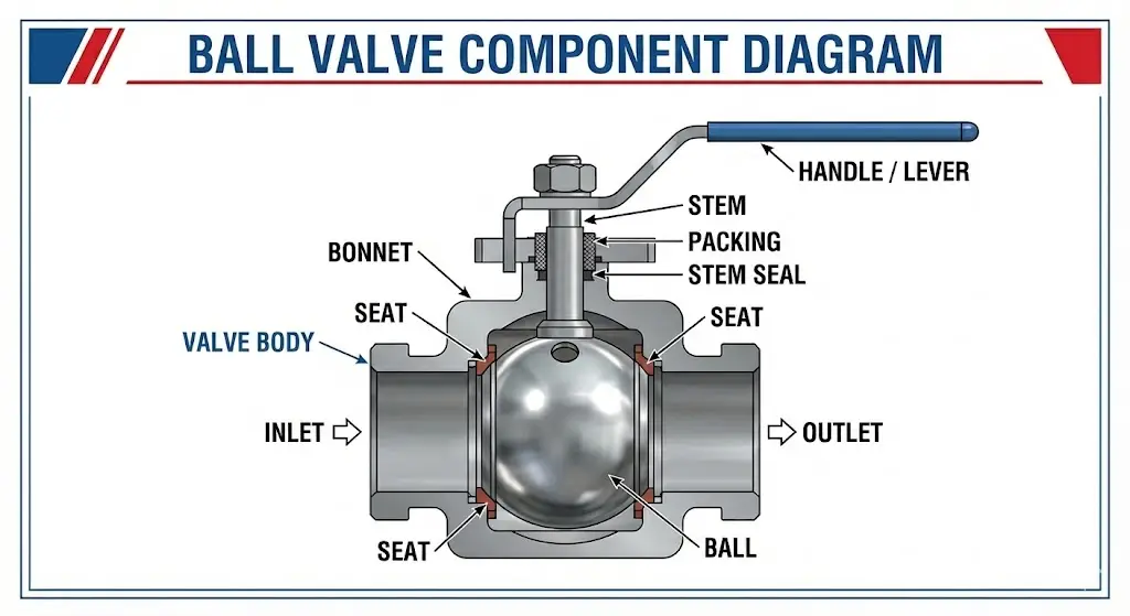
The valve stem is the drive shaft, which links the external valve handle or actuator to the internal ball. It conveys the force needed to spin the ball. Since the stem is piercing the pressure boundary of the valve, it is a possible leakage point and a safety issue.
Safety standards in industrial use require the use of an anti-blowout stem. In conventional designs, the internal pressure might theoretically blow out the stem in case the retaining nut becomes loose. An anti-blowout stem is made with a shoulder that fits within the valve body; the internal pressure causes the stem to be pushed firmly against the inside housing, and it is not ejected. This is a vital characteristic towards safety in hydraulic ball valves or systems that handle dangerous chemicals.
Seats, Seals, and Packing
The valve uses soft components in order to create a leak-proof system. The seal between the ball and the body is formed by the valve seat. They are usually rings of elastomeric or plastic in the shape of a donut.
- Valve Seats: These are found upstream and downstream sides of the ball. In the closed position, the ball pushes into these seats. The most popular seat material is PTFE (Polytetrafluoroethylene) because it has low friction and is highly compatible with chemicals.
- Stem Packing: This is found around the valve stem, and it is frequently in a stuffing box. This avoids the leakage of the stem area to the atmosphere.
- Body Seals: Gaskets that seal the joints between the valve body parts (e.g., where the end cap meets the body).
The choice of these internal factors is largely contingent on the temperature and chemical character of the media. As an example, a standard EPDM seal may be used in water treatment plants, but Viton or reinforced PTFE is needed in chemical plants to avoid degradation.
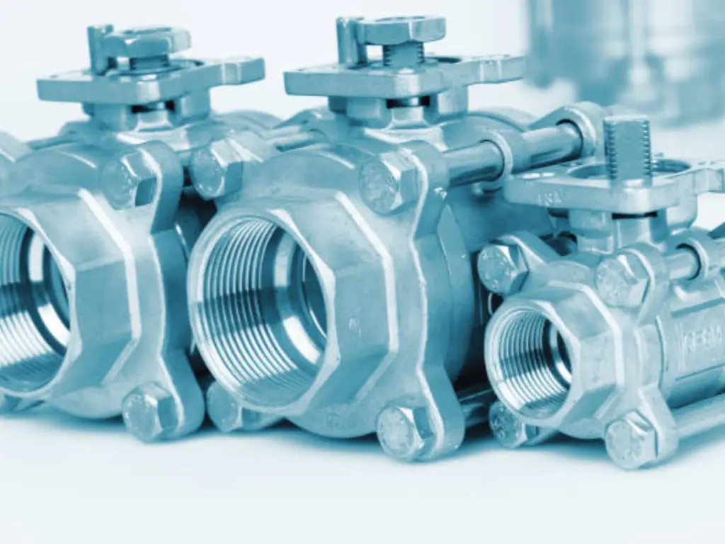
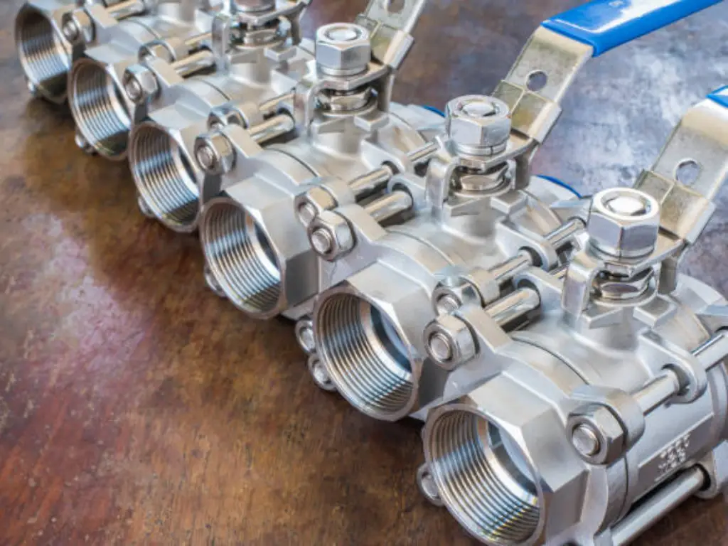
The Valve Body: Pressure Containment and Manufacturing
The primary outer shell that accommodates all internal components and links the valve to the piping system is the valve body. It is the main pressure-containing boundary and should be able to resist the mechanical forces of the pipeline, thermal expansion, and the pressure of the fluid. The integrity of the body structure is the most important; failure to this leads to disastrous leakage.
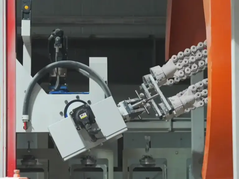
The final strength and reliability of the valve body is determined by the manufacturing process. Although there are low-cost valves that are forged or sand-cast, precision engineering requires greater production fidelity.
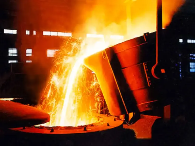
Why Investment Casting Ensures Superior Valve Bodies
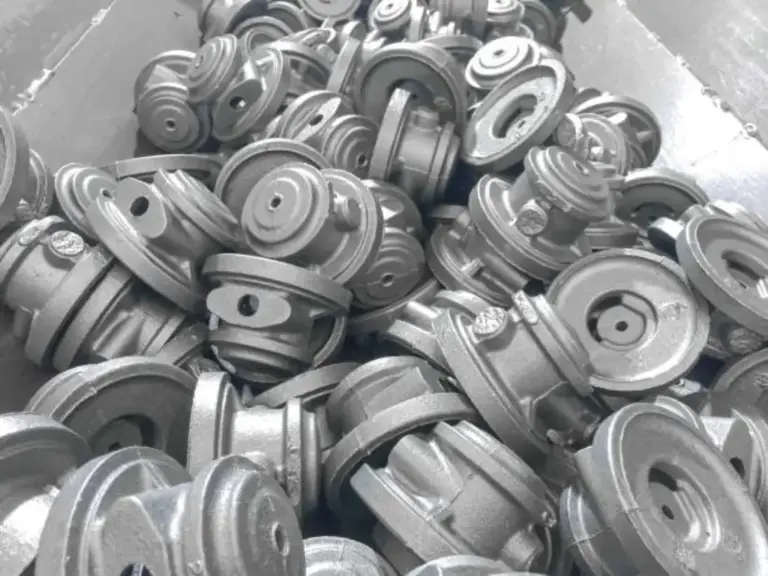
Investment casting (also called lost-wax casting) is the best manufacturing process to use in making valve bodies in cases where corrosion resistance and dimensional accuracy are non-negotiable. Investment casting, in contrast to sand casting, may leave a rough surface and porosity, but it results in a dense, homogeneous structure of metal with an outstanding surface finish.
The internal surface of a valve body is important to have a smooth surface to reduce turbulence and avoid the build-up of contaminants that may cause corrosion. In addition, the dimensional accuracy of investment casting is high, which makes it possible to use tight tolerances when assembling the valve seat and stem, which guarantees a flawless seal and a long service life.
Being a specialised manufacturer in this industry, Besser Cast employs modern investment casting methods to manufacture valve bodies that are of a high standard internationally. We have a very strict control over the composition of materials, be it stainless steel (CF8, CF8M) or Carbon Steel (WCB), to provide the end product with maximum durability and pressure containment. We offer valve solutions that are the backbone of the world’s valve manufacturers by removing the natural flaws that are common in the lower-grade casting techniques.
For detailed specifications on our manufacturing capabilities for valve parts, please visit https://www.bessercast.com/.
Body Construction Styles: 1-Piece, 2-Piece, and 3-Piece
The configuration of the valve body determines the ease of maintenance and the mechanical robustness of the unit. Valve designs generally fall into three categories based on how the body is assembled.
- One-Piece Ball Valve: The body is cast in one piece. The end connection is used to insert the internal components. This design produces a strong, leak-free body with reduced leak paths, but makes the valve non-repairable. If the seat is worn out, the whole valve should be changed. They are usually used in smaller sizes to run standard water flows.
- Two-Piece Ball Valve: It is the most widespread design in the industry. The body is made up of two components: the main body and an end cap. This enables bigger balls and full-bore openings. Although it is dismantlable, it is normally removed from the pipeline to be serviced.
- Three-Piece Ball Valve: This valve is designed to be used in critical fluid control systems and is made up of a central body section that holds the ball and the seats, which are sandwiched between two end caps (flanges or threaded ends). The unique feature is the swing-out: the technicians can loosen the bolts and swing the central body out to change the seats and seals without breaking the end connection with the pipe. This significantly minimises downtime in chemical processing or high-maintenance settings.
Material Selection Guide for Valve Parts
The choice of the right materials to use in the parts of the ball valves depends on the media, temperature, and pressure.
- Brass: Brass is commonly used as a water ball valve and domestic gas line because of its machinability and sufficient neutral media corrosion resistance.
- Stainless Steel (304/316): The industrial standard. It has a high level of corrosion resistance and high-pressure strength. Sanitary lines, chemical handling, and marine environments are necessary.
- Carbon Steel: This is used in high-pressure and high-temperature oil and gas applications where corrosion is not a major issue as compared to structural integrity.
- PVC & CPVC: These are plastic materials used in water treatment and corrosive chemical lines at low temperatures. They are light and cannot rust, yet have less structural strength as compared to metal.
Standards adherence is also crucial. In the case of potable water, the materials need to comply with the requirements of the Uniform Plumbing Code or the International Association of Plumbing and Mechanical Officials to guarantee lead-free composition.
Actuation Methods: Handle and Actuator
The actuator is the mechanism that rotates the stem. The most basic type of actuation of manual ball valves is the valve handle (or lever). The handle position gives a visual cue of the valve position immediately: when the handle is parallel to the pipe, the valve is open; when it is perpendicular, the valve is closed.
But in complicated fluid control systems, manual control is not efficient. Pneumatic actuators (which use air pressure) or electric actuators are fitted to the top of the valve. These are devices that are attached to the stem and can be controlled remotely or automatically. To enable this, the valve body frequently has an ISO 5211 mounting pad, a standardised interface that enables actuators to be bolted onto the valve without alteration.
Diagnosing Issues Based on Part Failure
Knowledge of the components of a ball valve can be of great help in troubleshooting. A failure of a particular component may have a characteristic symptom:
| Observable Symptom | Probable Failed Part | Root Cause | Recommended Action |
| Leakage at the Stem (Fluid leaking from under the handle) | Stem Packing / O-rings | Normal wear and tear; Loose packing nut. | Tighten the packing nut (if available on the gland). If leakage persists, the packing material requires replacement. |
| Internal Leakage (Passing) (Fluid flows downstream while in Closed Position) | Valve Seat / Ball Surface | Abrasive particles in the fluid have scratched the soft PTFE seat or the polished ball surface. | The valve requires disassembly. Damaged seats must be replaced. Check if the ball surface needs re-polishing or replacement. |
| Stuck Valve (Handle is difficult or impossible to turn) | Ball-to-Seat Interface | Accumulation of debris between the ball and body; Swelling of seats due to incorrect chemical compatibility. | Flush the valve to remove debris. If swelling occurred, replace seats with a more compatible material (e.g., changing from PTFE to PEEK). |
| Body Leakage (Leakage from joints or the shell itself) | Body Seals / Valve Body | Loose body bolts; Failed body gaskets; Casting porosity (in low-quality valves). | Tighten body bolts or replace seals. If the leak is through the metal wall (porosity), the entire body must be replaced. Mitigation: Source high-quality investment castings. |
Conclusion
The ball valve is a misleadingly simple device that is made up of highly engineered parts. Since the primary outer shell (the body) to the fine-tuning of the rotary ball, and the safety measures of the stem are all components that are important in the integrity of fluid control systems.
The principles of operation are similar, whether it is hydraulic ball valves with thousands of pounds of pressure or simple PVC and CPVC valves used in irrigation. To engineers and procurement specialists, the best approach to the longevity of the system is to focus on the quality of the valve body and internal trim. With the help of the precision-manufactured components, including the investment castings offered by Bessercast, the industries will be able to obtain the valve solutions that will provide the best performance, safety, and reliability in all the specific applications.