The Ultimate Guide to Investment Casting Wax: Types, Properties & Defect Control
In the highly precise world of investment casting, the final quality of a metal component is inextricably linked to its very first physical manifestation: the wax pattern. While often dismissed as a basic, consumable supply in the broader supply chain, investment casting wax is fundamentally an engineered material. Its thermophysical properties dictate the boundaries of your dimensional accuracy, surface finish, and overall production yield.
For B2B procurement managers, foundry engineers, and supply chain directors in aerospace, automotive, and medical industries, understanding the nuances of pattern wax is not just an academic exercise—it is a critical commercial imperative. A miscalculation in wax shrinkage or ash content can trigger a cascade of defects, transforming a cost-saving material decision into a catastrophic spike in scrap rates and post-machining costs. This comprehensive guide dissects the types, critical properties, and troubleshooting methodologies of investment casting wax, providing you with the engineering insights needed to control defects at the source.
The Hidden Foundation: Why Investment Casting Wax Dictates Your Final Yield
To understand the true value of investment casting wax, we must shatter the illusion that it is merely a cheap placeholder. The fundamental principle of the lost-wax casting process is dimensional transfer fidelity. The wax pattern is the only positive replica of your final part. Every microscopic air bubble, every fraction of a millimeter of sink mark, and every subtle flow line on the wax pattern will be mercilessly transferred—and often magnified—onto the final metal casting.
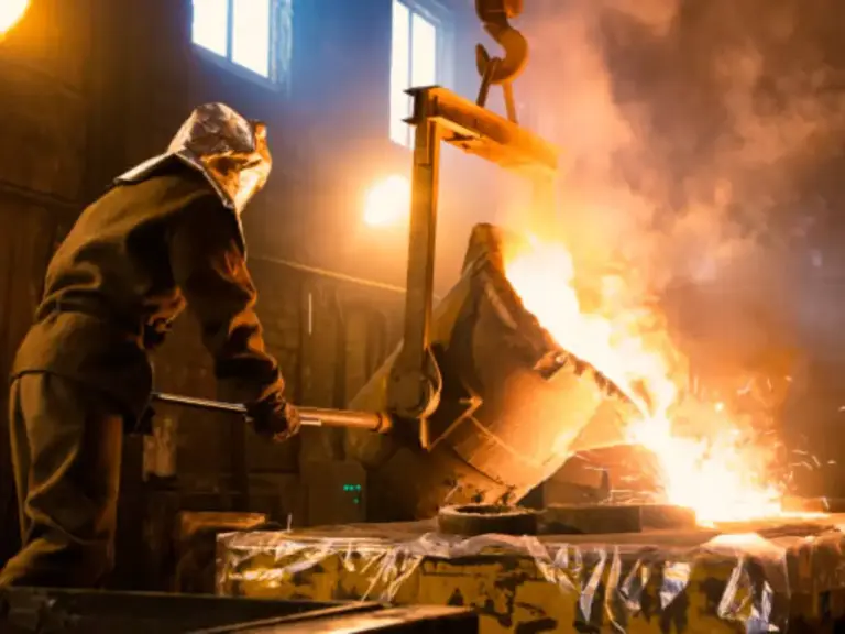
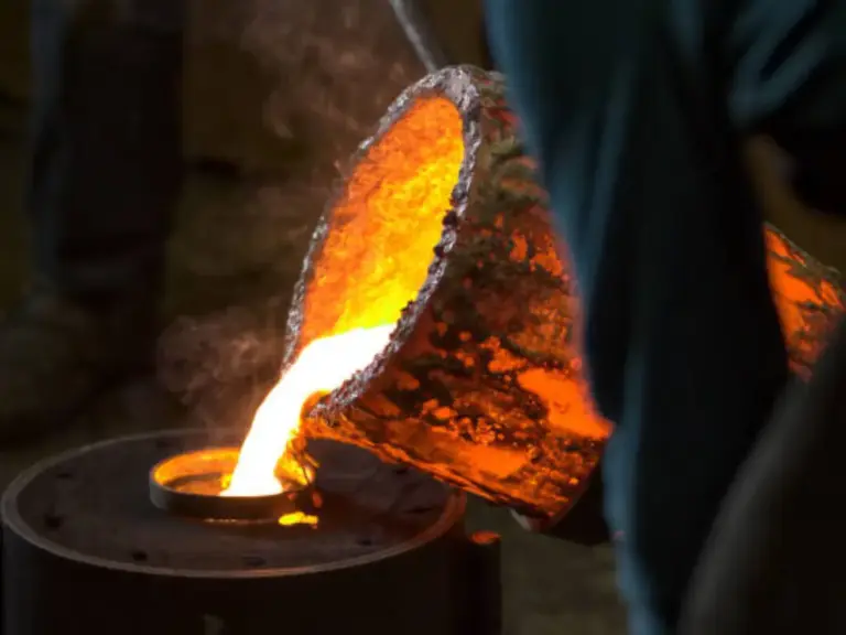
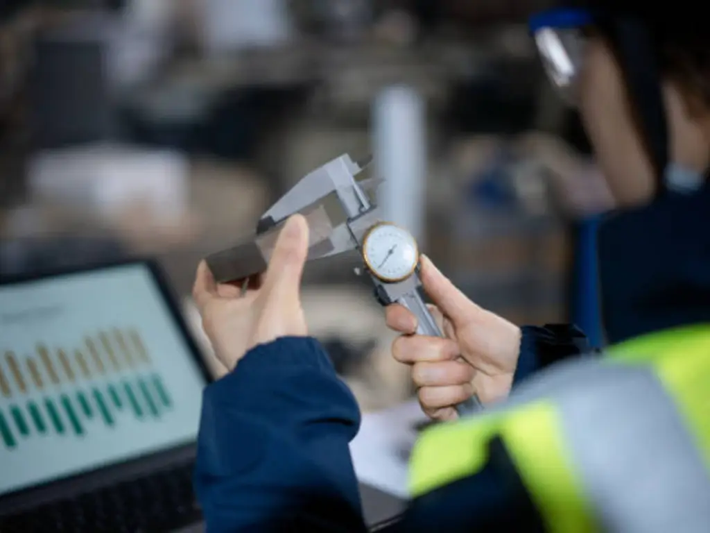
Consider the financial realities of modern foundry operations. Let’s look at an aerospace-grade aluminum alloy valve body. The final machined component might carry a market value of $500 to $800. The ceramic shell materials, the vacuum melting process, and the CNC machining required to finish it represent massive investments of energy and time. Yet, the root cause of this $500 component failing its final CMM (Coordinate Measuring Machine) inspection is frequently traced back to a wax pattern that cost less than $0.50 to produce.
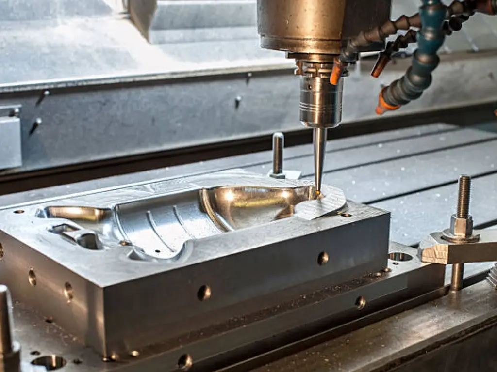
When a wax pattern suffers a 0.1mm cavitation due to improper cooling or poor material stability, the ceramic shell forms precisely around that defect. The molten metal then fills that exact flawed geometry. By the time the defect is discovered during post-machining or X-ray inspection, thousands of dollars in value-added processing have already been wasted. Therefore, optimizing your wax selection and injection parameters is the highest-leverage activity a foundry can undertake to protect its final yield rate.
Primary Types of Investment Casting Wax: A Functional Matrix
Not all casting waxes are created equal. The industry categorizes waxes based on their specific function within the assembly tree. Selecting the wrong category for a specific geometric feature is a guaranteed path to dimensional failure.
Pattern Waxes and Filled Waxes
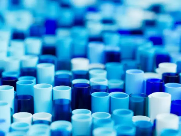
Pattern waxes are the primary materials used to create the actual geometry of the desired metal part. Among these, Filled Waxes are the industry standard for high-precision components. To combat the natural volumetric shrinkage of pure wax as it cools from a liquid to a solid state, manufacturers blend in solid fillers—typically cross-linked polystyrene, water-soluble organic acids, or sophisticated resins.
These fillers usually constitute 20% to 40% of the wax volume. Think of pure wax as water turning into ice; the volumetric change is significant and hard to control. Filled wax, however, acts more like concrete. By suspending solid “aggregate” (fillers) within the liquid wax matrix, the overall shrinkage during solidification is drastically minimized. However, this dimensional stability comes at a cost: fillers increase the melt viscosity. Highly filled waxes require higher injection pressures and carefully engineered mold venting to successfully fill ultra-thin walls without causing incomplete fills (non-fill defects).
Soluble Waxes for Complex Cavities
When designing parts with intricate internal geometries—such as closed impellers, hydraulic pump internal channels, or turbine blade cooling passages—standard ceramic coring is often impossible or prohibitively expensive. This is where Soluble Waxes are deployed.
Soluble waxes are formulated from weak organic acids and are designed to dissolve rapidly when exposed to mild acidic aqueous solutions (such as a citric acid bath). In practice, a soluble wax core is injected first. This core is then placed inside the main pattern die, and standard pattern wax is injected around it. Before the ceramic shell building process begins, the entire assembly is submerged in an acid bath. The soluble core dissolves, leaving behind a perfect, complex internal cavity within the pattern wax. The primary challenge with soluble waxes is their hygroscopic nature; they absorb moisture from the air, meaning tight environmental controls are required during storage and assembly to prevent dimensional swelling.
Auxiliary Waxes: Runner, Sprue, and Sticky Wax
To transform individual wax patterns into a castable format, they must be assembled onto a central gating system (the tree). This requires specialized auxiliary waxes.
| Wax Category | Primary Function | Key Additives / Composition | Critical Requirement | Relative Cost |
|---|---|---|---|---|
| Runner/Sprue Wax | Forms the central gating system to deliver molten metal. | Hydrocarbon resins, lower melting point waxes. | Must melt out before the pattern wax to prevent shell cracking. High mechanical strength. | $2.50 – $5.50 / kg |
| Sticky Wax | Adhesive used to weld patterns to the runner system. | Tackifying resins, beeswax. | Extreme room-temperature tensile strength to survive robotic dipping without dropping parts. | $8.00 – $16.00 / kg |
| Patching Wax | Repairing minor surface defects on patterns before shelling. | Soft, highly malleable microcrystalline waxes. | Must blend seamlessly with pattern wax; leaves absolutely zero ash residue. | $10.00 – $22.00 / kg |
Critical Thermophysical Properties: Beyond the Spec Sheet
Reviewing a wax supplier’s technical data sheet requires looking past basic melting points. Engineers must focus on the thermophysical properties that directly interact with the ceramic shell and the final molten metal.
Ash Content and Shell Reaction
In the investment casting process, the wax is evacuated from the ceramic shell using a steam autoclave, followed by a high-temperature burnout oven (often exceeding 1000°C) to sinter the shell. Any inorganic material present in the wax that does not combust and vaporize is left behind as Ash Content.
Ash is a silent killer of castings. It forms microscopic residues on the inner walls of the ceramic cavity. When molten metal is poured, these residues become trapped in the metal surface, creating severe inclusion defects that ruin the surface finish and compromise the mechanical integrity of the part. According to standard testing protocols (such as ASTM D2584 or ICI standards for ash determination), standard commercial castings might tolerate up to 0.05% ash. However, for critical applications like aerospace turbine blades or high-stress automotive components, ash content must be ruthlessly controlled to < 0.01% to 0.02%.
Volumetric Shrinkage and Dimensional Stability
As wax transitions from a molten state to room temperature, it shrinks. Typically, volumetric shrinkage ranges from 1% to 2% depending on the formulation. Many inexperienced buyers assume that dimensional inaccuracies in their final parts are solely due to the shrinkage of the cooling metal. In reality, the most unpredictable variables often lie in the inconsistent shrinkage of the wax pattern.
The Engineering Reality: For top-tier foundries like Besser Casting, achieving the stringent CT4 European tolerance standard isn’t about luck or just tweaking CNC machines. It is about strictly controlling wax shrinkage down to an astonishing 0.1%.
By utilizing highly stable, premium filled waxes and meticulously controlling injection temperatures within fractions of a degree, foundries can lock in the dimensional integrity of the pattern. When you stabilize the wax shrinkage at 0.1%, you eliminate the compounding errors that traditionally plague the lost-wax process. This extreme material control is the foundational prerequisite for delivering CT4 tolerances reliably across thousands of production cycles.
Melt Viscosity and Flowability
Viscosity determines how well the liquid wax will flow into the intricate details of the aluminum die under pressure. Wax is typically injected in a “pastry state” (semi-solid/slush) or a near-liquid state, usually within a tight temperature window of 60°C to 70°C.
If the viscosity is too high (wax is too cold or filler content is too dense), the wax will freeze before reaching the extremities of the mold, resulting in rounded edges and non-fill defects. Conversely, if the viscosity is too low (wax is too hot), it can flash into the parting lines of the tooling, requiring excessive manual trimming. Furthermore, low-viscosity wax is prone to turbulent flow during injection, which traps air and creates subsurface bubbles that will inevitably ruin the casting’s surface.
The Reclaimed vs. Virgin Wax Dilemma in B2B Foundries
For B2B procurement, cost control is paramount. This brings us to the industry’s most debated topic: the use of Virgin Wax versus Reclaimed (Recycled) Wax. Because wax is melted out of the shells, a significant portion can be recovered. Reclaimed wax is significantly cheaper, but its physical properties degrade with every thermal cycle. It loses volatile organics, becomes brittle, and accumulates microscopic ceramic contaminants.
The strategic rule for high-end foundries is absolute segregation. 100% virgin wax must always be used for critical pattern generation. Reclaimed wax, after undergoing rigorous filtration and de-watering processes, should be strictly downgraded and repurposed exclusively for the runner and sprue systems. Some foundries may blend 10% to 20% highly purified reclaimed wax into bulk patterns for non-critical industrial weights, but utilizing reclaimed wax for complex, thin-walled, or high-tolerance components is a false economy that will obliterate your yield rate.
The Dewaxing Phase Physics: Preventing Shell Cracking
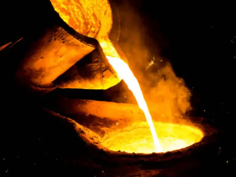
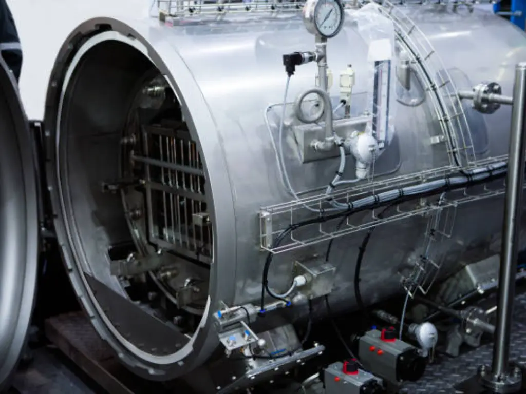
One of the most catastrophic failures in a foundry is shell cracking during the dewaxing process. To prevent this, one must understand the physics of Thermal Expansion Mismatch. Wax expands at a rate significantly higher than the ceramic shell encasing it. If a shelled wax tree is placed into a slow-heating oven, the wax core will expand radially, acting like a hydraulic wedge that shatters the fragile green ceramic shell from the inside out.
To counteract this, the industry utilizes the Autoclave—a high-pressure steam vessel. The goal is Flash Melting. By injecting high-temperature steam (typically 150°C – 180°C at 8-10 bar pressure) in a matter of seconds, the intense thermal shock instantly melts the outermost skin of the wax that is touching the ceramic. This liquid wax immediately drains out, creating a microscopic void. This void provides the crucial “expansion room” for the internal solid wax core as it subsequently heats and expands, thereby saving the ceramic shell from rupture.
Troubleshooting Common Wax Pattern Defects
When defects occur, rapid diagnosis is required to keep production lines moving. Here is a practical troubleshooting guide for the most common wax-related failures.
Flow Lines and Non-Fill (Knit Lines)
Phenomenon: Visible ripples, overlapping lines on the surface of the wax, or incomplete geometries at the furthest edges of the part.
Root Cause & Solution: This indicates the wax cooled too rapidly before fusing together.
- Temperature: Increase the wax injection temperature or the aluminum die temperature to maintain flow.
- Pressure: Increase injection pressure to force the material into thin sections faster.
- Venting: Check the tooling. If air cannot escape the die, wax cannot enter. Ensure vents are clean and properly sized.
Sink Marks and Cavitation
Phenomenon: Depressions on flat surfaces or large internal voids within thick cross-sections of the wax pattern.
Root Cause & Solution: Caused by the natural volumetric shrinkage of the wax as it solidifies. The outer skin freezes first, and as the liquid core cools and shrinks, it pulls the skin inward.
- Dwell Time: Increase the injection dwell time (holding pressure) to continuously feed liquid wax into the die as the pattern shrinks.
- Material Swap: Switch to a highly filled wax formulation with lower inherent shrinkage.
- Tooling Adjustments: Utilize aluminum or copper chills in the die to accelerate cooling in thick sections, promoting uniform solidification.
Beyond Sourcing: Why Your Foundry’s Wax Management Matters More Than the Wax Itself
Ultimately, as a buyer or engineer, your goal is not to become an expert in purchasing raw wax. Your objective is to source flawless metal components. Struggling with inconsistent dimensions, rough surfaces, or agonizingly long lead times from your current supplier? The root cause is rarely the brand of wax they use; it is hidden in their inability to control the wax injection and subsequent shell-making processes.
Mediocre foundries rely on manual labor, inconsistent wax preparation, and cheap recycled materials. Top-tier foundries integrate precision wax control with cutting-edge automation.
At Besser Casting, we understand that a perfectly injected wax pattern demands an equally perfect ceramic shell. To ensure we never compromise on the fidelity of our wax patterns, we have invested heavily in fully automated shell-making production lines. This technology compresses the traditional 7-day manual shelling cycle down to just 35 hours. This doesn’t just solve your lead-time headaches; it provides an ultra-stable, machine-controlled ceramic environment that flawlessly captures every detail of our 0.1% shrinkage wax.
Combined with our in-house German Spectro spectrometers, Swedish Hexagon CMMs, and strict adherence to imported silica sol materials, we routinely deliver castings with surface finishes of Ra 3.2 or better—meeting the exacting standards of global leaders like John Deere and Alstom.
Don’t let poor wax management at your current foundry dictate your scrap rates. Leverage our 15-person R&D team and advanced Casting Simulation Software to identify risks before a single die is cut. Contact Besser Casting today for a comprehensive DFM (Design for Manufacturing) analysis of your next critical project, and experience the yield stability that comes from absolute process control.