Steel Investment Casting: The Ultimate Engineering & Cost Guide
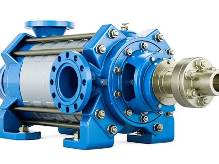
Before diving into the step-by-step mechanics, we must establish why steel investment casting is fundamentally different from rudimentary metalworking. Historically rooted in the creation of ancient art and jewelry—where the “lost-wax” technique was born—today’s industrial application is a highly controlled science. When an engineer specifies steel, they are usually dealing with high-stress applications: explosive pressures inside a hydraulic manifold, corrosive attacks on a marine impeller, or the relentless fatigue cycles of an agricultural gearbox. In these environments, “close enough” is a recipe for catastrophic failure.
The true power of this process lies at the exact intersection of metallurgy and geometric precision. It allows designers to consolidate what would normally be an assembly of four or five welded or bolted machined parts into a single, monolithic steel structure. By doing so, you eliminate weld seams (which are inherent stress concentrators), reduce the overall weight of the component, and drastically cut down the bill of materials (BOM). However, this consolidation means the foundry must master the chaotic behavior of liquid steel as it rapidly cools and shrinks within a complex ceramic cavity. Understanding this dynamic is the first step toward successful part design.
In the modern manufacturing landscape, the demand for high-performance, intricately designed metal components is at an all-time high. Yet, navigating the world of steel investment casting is not merely about melting metal and pouring it into a mold. It is a highly sophisticated intersection of fluid dynamics, thermodynamics, and precision machining. Many procurement managers and design engineers fall into the trap of over-specifying tolerances or choosing the wrong alloy, resulting in skyrocketing tooling costs and unacceptable defect rates.
This comprehensive guide is designed to tear down the marketing fluff and provide you with hard, actionable engineering data. We will explore the fundamental mechanics of the four-stage process, dive deep into the metallurgical matrix of stainless and carbon steels, map out the true economic inflection point between casting and CNC machining, and equip you with the Design for Manufacturability (DFM) principles needed to optimize your next major production run.
Decoding Steel Investment Casting: The Intersection of Metallurgy and Precision
The Four Fundamental Phases of the Lost-Wax Process
To truly understand the value of steel investment casting, we must first deconstruct its underlying mechanics. Unlike sand casting, which uses a reusable pattern to pack a disposable sand mold, investment casting utilizes a disposable pattern to create a highly precise, disposable ceramic mold. To achieve a comprehensive understanding, the process must be viewed through four distinct, non-overlapping phases: Tooling and Pattern Creation, Shell Building, High-Temperature Pouring, and Post-Processing & Heat Treatment.
1. Tooling and Pattern Creation: The journey begins with a precision-machined aluminum die. Molten wax is injected into this die under high pressure to create a perfect replica of the desired final part. Engineers must calculate complex “shrinkage allowances” into this die, as both the wax and the eventual steel will contract upon cooling. These wax patterns are then attached to a central wax sprue, forming a structure known as a “tree.”
2. Shell Building (Investing): The magic happens during the shell-building phase. The wax tree is dipped into a liquid ceramic slurry (often colloidal silica) and then coated with fine refractory sand. This dipping and stuccoing process is repeated multiple times in strictly climate-controlled drying rooms. Once the shell reaches the required thickness, the entire assembly is placed into an industrial autoclave. Pressurized steam rapidly melts the wax out (hence, “lost-wax”), leaving a hollow ceramic cavity that perfectly mirrors the original CAD design.
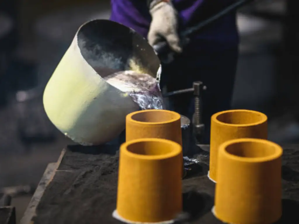
3. High-Temperature Pouring: Crucially, before any metal can be poured, this ceramic shell must undergo a severe high-temperature firing process, exceeding 1000°C (1832°F). This completely incinerates any residual wax that could cause explosive outgassing and drastically increases the yield strength of the ceramic. While the shell is still red-hot, molten steel is poured into the cavity, minimizing thermal shock and allowing the liquid metal to flow into ultra-thin sections before freezing.
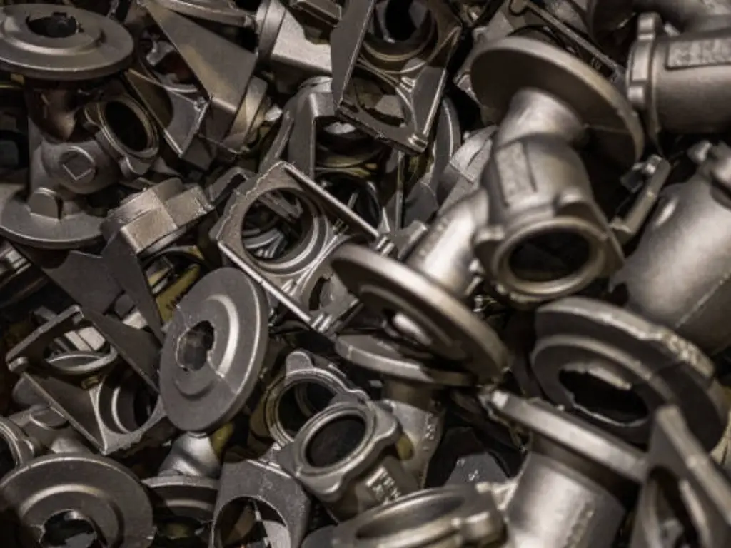
4. Post-Processing & Heat Treatment: The casting process does not end when the metal solidifies. The ceramic shell is violently shattered and removed via pneumatic hammers and shot blasting (Knockout). The individual parts are then cut from the central sprue using abrasive friction saws. Finally, the raw castings undergo critical thermal cycles—such as normalizing, quenching, or annealing—to relieve internal residual stresses accumulated during rapid cooling and to achieve the targeted mechanical properties.
Why Steel Changes the Equation Compared to Other Metals
Introducing steel into the investment casting equation fundamentally changes the rules of physics. Pouring aluminum or brass is relatively forgiving due to their lower melting points. Steel, however, demands an entirely different level of engineering respect. The pouring temperature for steel alloys typically ranges between 1550°C and 1650°C (2822°F – 3002°F).
To put this into perspective, pouring liquid steel is akin to pouring active volcanic magma into a delicate glass cup. At these extreme temperatures, the liquid steel becomes highly reactive. If the ceramic shell is not engineered correctly, a phenomenon known as “metal-mold reaction” occurs, where the steel chemically bonds with the ceramic, destroying the surface finish and ruining the dimensional accuracy. To prevent this, top-tier foundries must utilize incredibly expensive and highly stable refractory materials for the “face coat” (the very first layer of the ceramic shell that touches the metal). Materials like imported Zircon (zirconium silicate) or fused corundum are mandatory. This extreme thermodynamic challenge directly explains why the initial piece price of a steel investment casting carries a premium over non-ferrous metals.
Navigating Steel Alloys for Investment Casting: A Metallurgical Matrix
One of the greatest advantages of the investment casting process is its almost limitless metallurgical flexibility. Unlike forging or die casting, which are restricted by the plasticity or melting points of the metals, investment casting can accommodate virtually any alloy. However, selecting the right alloy is not just about looking up mechanical properties in a textbook; it is about understanding how that specific chemistry behaves during solidification. All material selections should strictly reference international standards, such as those governed by ASTM International.
The Stainless Steel Family: Austenitic, Martensitic, and Duplex
Stainless steel is the undisputed king of investment casting, prized for its corrosion resistance. However, engineers must understand the profound differences in castability and operational performance across its distinct microstructures.
| Alloy Grade | Microstructure | Castability (Fluidity) | Key Properties | Ideal Applications |
|---|---|---|---|---|
| 304 / 316L | Austenitic | Excellent | Supreme general corrosion resistance, non-magnetic, highly ductile. | Food processing equipment, chemical pipe fittings, medical devices. |
| 17-4PH (CB7Cu-1) | Martensitic (Precipitation Hardening) | Poor to Fair | Extremely high yield strength, excellent hardness after heat treatment. | Surgical instruments, aerospace structural brackets, pump shafts. |
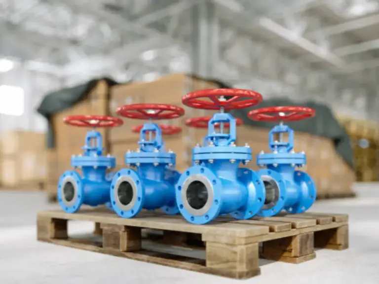
| 410 / 420 | Martensitic | Fair | High hardenability, moderate corrosion resistance, wear-resistant. | Industrial cutting blades, high-wear fluid valve components. |
| Duplex 2205 (CD3MN) | Austenitic-Ferritic (Mixed) | Fair to Good | Double the yield strength of 316L, exceptional resistance to chloride Stress Corrosion Cracking (SCC). | High-pressure marine impellers, offshore oil & gas valves, desalination plants. |
From a manufacturing perspective, Austenitic grades like 304 and 316L are highly fluid, allowing them to fill incredibly thin walls. However, a common metallurgical misconception occurs regarding their marine performance. If a batch of 316L rusts prematurely in a chloride-rich marine environment, the root cause is rarely a lack of Nickel. Instead, resistance to Pitting Corrosion is dictated by its critical Molybdenum (Mo) content (typically strictly controlled between 2.0% and 3.0%). If the foundry skimps on Molybdenum, the alloy’s Pitting Resistance Equivalent Number (PREN) plummets, rendering it vulnerable to the aggressive attack of seawater, regardless of how much Nickel is present.
For extreme offshore applications where 316L’s yield strength falls short, Duplex Stainless Steels (like 2205) offer the ultimate upgrade. By maintaining a roughly 50/50 split of austenite and ferrite phases, Duplex alloys deliver massive structural strength alongside immunity to chloride stress-corrosion cracking—a mandatory requirement for modern high-pressure subsea valves.
Carbon Steels and Low Alloy Steels for High-Stress Scenarios
When extreme corrosion resistance is not the primary requirement, but massive yield strength, impact toughness, and lower raw material costs are paramount, engineers turn to low alloy steels like 4140. For example, specifying 304 stainless steel for an earth-moving excavator lug results in massive performance overkill and inflated costs. By shifting to a 4140 investment casting, raw material costs are instantly slashed.
However, carbon and low-alloy steel castings carry a strict caveat: their as-cast microstructure is often coarse and brittle. To unlock their true potential, they must undergo rigorous full-body heat treatment. A common and critical process for 4140 is Quenching and Tempering. It is vital to note that this is a through-hardening process, not mere surface hardening (like carburizing). The casting is heated to its austenitizing temperature, rapidly quenched in oil or polymer to form extremely hard but brittle untempered martensite, and then reheated (tempered). This precise thermal choreography transforms the entire cross-section of the component into tempered martensite, achieving the ultimate, homogeneous balance of high ultimate tensile strength and excellent impact toughness required to survive heavy industrial shock loads.
Design for Manufacturability (DFM): Engineering Beyond Basic Tolerances
The most expensive mistakes in investment casting are not made on the foundry floor; they are made on the CAD screens of design engineers. A part that looks mathematically perfect in SolidWorks can turn into a scrap-generating nightmare in reality. To bridge the gap between theoretical design and physical metallurgy, we must establish strict Design for Manufacturability (DFM) rules.
Wall Thickness, Radii, and Preventing Hot Tearing
Steel is not plastic. You cannot simply inject it into infinitely thin cavities. As a general engineering rule, the absolute minimum wall thickness for standard atmospheric steel investment casting should not fall below 1.5mm to 2.0mm. Anything thinner risks a “misrun,” where the liquid steel freezes before it can completely fill the ceramic cavity.
Furthermore, the handling of corners and transitions is a matter of life and death for a casting. Sharp internal corners (90-degree angles with zero radius) are strictly forbidden. Let’s simulate a common error: an engineer designs a high-pressure valve seat with a perfect, sharp 90-degree internal corner. As the molten steel solidifies, it shrinks volumetrically. The metal on both sides of that corner pulls towards its respective center of mass. This creates a massive concentration of tensile stress exactly at the sharp corner. Because the metal is still scorching hot and structurally weak, it literally tears itself apart inside the ceramic shell—a fatal defect known as “hot tearing.” Simply adding a generous internal fillet radius (minimum R1.5 to R3.0) perfectly disperses this stress, allowing the part to shrink uniformly without fracturing.
The Reality of CT4 to CT6 Dimensional Tolerances
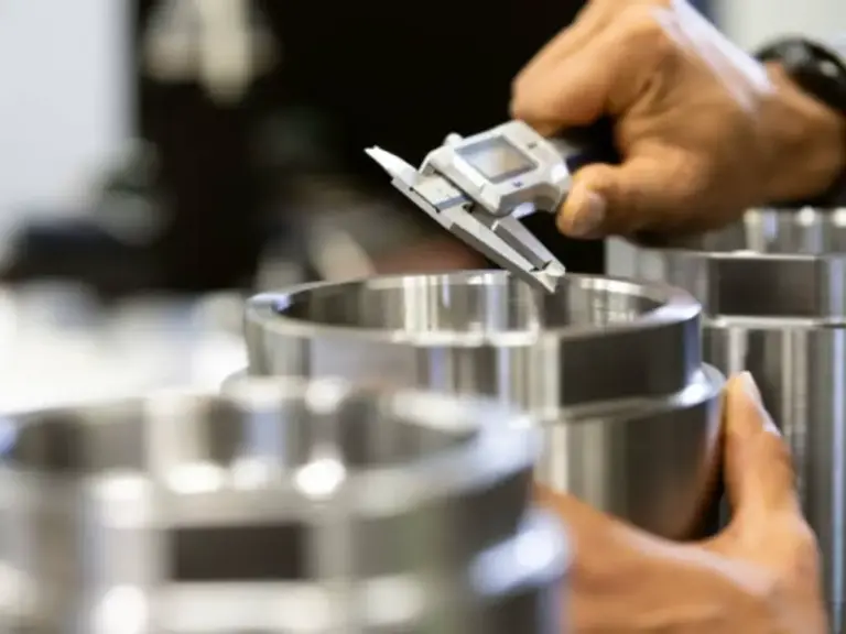
It is time to address the elephant in the room: dimensional tolerances. Many foundries aggressively market their ability to achieve “perfect” tolerances, misleading buyers into thinking investment casting can completely replace precision CNC machining. The objective truth, governed by standards like ISO 8062, is that steel shrinks unpredictably based on geometry (typically 2% to 2.5%).
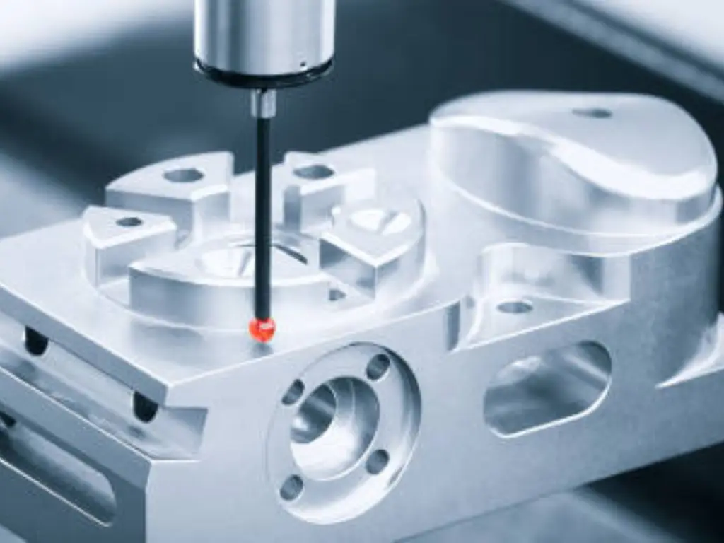
For small dimensions (under 25mm), achieving a tight tolerance of ±0.13mm is highly feasible. However, on a 150mm dimension, the natural shrinkage of steel will push the tolerance band out to ±0.75mm or more. Smart engineers do not force the foundry to cast the entire part to a CT4 (extremely tight) tolerance. The most cost-effective strategy is to cast the bulk of the part to a stable CT5 or CT6 level, while leaving a small 0.8mm machining allowance strictly on critical bearing fits or sealing grooves for a final, lightning-fast CNC turning operation.
The Besser Casting Advantage: Redefining the Tolerance Baseline
Why do so many foundries fail to even maintain CT6, resulting in warped parts and delayed shipments? The hidden truth is that 70% of dimensional instability and surface defects originate from a single, chaotic variable: manual shell building and cheap domestic slurry. When workers manually dip wax trees, the ceramic thickness is inherently uneven, leading to irregular cooling rates and unpredictable shrinkage.
Recognizing that stability is the core of precision, Besser Casting completely eliminated manual variables by investing heavily in two fully automated, robotic shell-building production lines—a rarity possessed by less than 5% of foundries globally. Paired exclusively with premium imported silica sol and zircon powder, this automation ensures mathematically perfect shell thickness. As a result, Besser Casting is able to control wax shrinkage to an astonishing 0.1%, pushing the boundaries of as-cast tolerances closer to the elusive CT4 level, while simultaneously delivering an exceptionally smooth Ra 3.2-6.3 surface finish. Furthermore, this automation crushes lead times, slashing the traditional 7-day shell drying cycle down to an unprecedented 35-36 hours, providing buyers with absolute supply chain certainty.
The Economic Inflection Point: Investment Casting vs. Alternative Methods
For procurement managers, every engineering decision must eventually answer one question: “What is the Total Cost of Ownership (TCO)?” Investment casting is famous for its high initial tooling costs (often ranging from $2,000 to $6,000 for complex aluminum dies). To justify this CapEx to the financial board, we must calculate the exact economic inflection point and evaluate the critical balance of time versus precision.
Precision vs. Speed: Investment Casting vs. Sand Casting
When buyers see the tooling cost of investment casting, they often ask, “Why not just use sand casting for cheaper?” To answer this, we must objectively evaluate the trade-off between speed and operational precision.
From a pure speed perspective, sand casting is undeniably faster in the prototyping phase. A sand foundry can often deliver a first article sample within 1 to 2 weeks. In contrast, precision investment casting naturally requires 4 to 6 weeks for initial sampling. This is not due to inefficiency, but rather the immutable laws of chemistry: the multiple layers of the ceramic shell require meticulous, slow drying in climate-controlled rooms to prevent cracking.
However, what you sacrifice in initial weeks, you gain back tenfold in long-term assembly efficiency. Sand casting typically yields a rough surface texture ranging from Ra 12.5 to Ra 25. Visually, it looks like a coarse asphalt road. Investment casting, thanks to the incredibly fine zircon slurry, achieves an Ra 3.2 to Ra 6.3 finish—resembling a smooth, matte ceramic tile. If your component is a pump housing moving high-velocity fluids, the “asphalt” surface of a sand casting will cause massive fluid turbulence and efficiency loss. To fix it, you would have to pay workers to manually grind and polish the complex internal channels—a labor-intensive nightmare that quickly erases any initial lead-time or cost savings. By accepting the 4-6 week lead time of investment casting, you eliminate secondary internal polishing entirely.
Cost Crossover Matrix: Investment Casting vs. CNC Machining
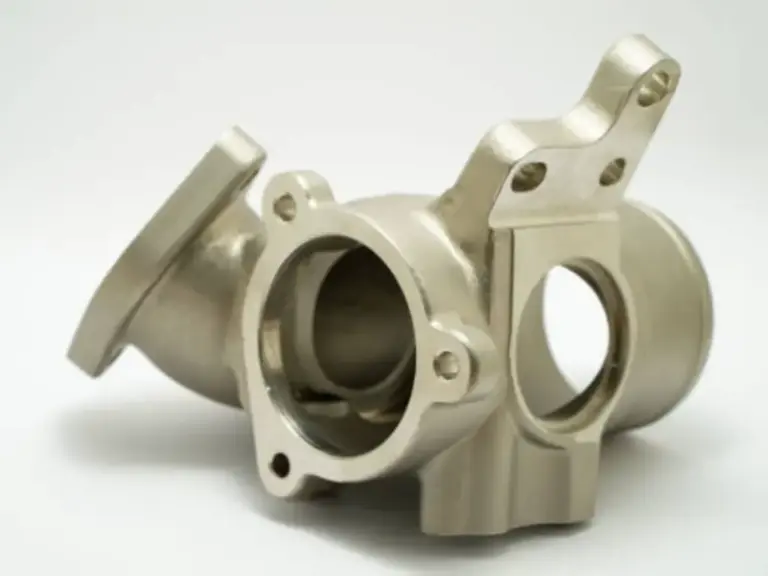
Let us run a real-world cognitive sandbox. Imagine a 1.5kg stainless steel 316L fluid control valve body featuring internal fluid channels, multiple flanges, and a complex contoured exterior. CNC machining this part from a solid billet of 316L means a Material Removal Rate (MRR) of nearly 60%. You are paying for expensive stainless steel only to turn it into scrap chips, while burning through expensive carbide end-mills due to 316L’s notoriously rapid tool wear. Assuming a $3,500 tooling cost for investment casting, let’s look at the break-even math:
| Production Volume | Pure CNC Cost (Per Unit) | Investment Casting Cost (Unit + Tooling Amortization) | The Economic Winner |
|---|---|---|---|
| 50 Units (Prototype run) | $180.00 | $45.00 + ($3500/50) = $115.00 | Investment Casting (Tooling pays off incredibly early) |
| 500 Units (Low-volume) | $165.00 | $40.00 + ($3500/500) = $47.00 | Investment Casting (Cost drops by over 70%) |
| 2,000 Units (Mass production) | $150.00 | $35.00 + ($3500/2000) = $36.75 | Investment Casting (Absolute domination) |
*Note: The cost breakdown above is a theoretical baseline for a mid-complexity, 3-axis equivalent geometry. Actual TCO (Total Cost of Ownership) savings scale exponentially with part complexity. For 5-axis equivalent geometries, the break-even point occurs even sooner.*
Quality Assurance Protocols: Validating Internal Integrity
B2B buyers share a common nightmare: receiving a batch of castings that look flawless on the outside, only to have them fail catastrophically in the field due to hidden internal shrinkage cavities. Trust in manufacturing cannot be built on visual inspections alone; it requires scientific validation.
Non-Destructive Testing (NDT) and Radiographic Inspection
To guarantee internal integrity, rigorous Non-Destructive Testing (NDT) is non-negotiable. For critical components like high-pressure manifolds or aerospace brackets, Radiographic Testing (RT), commonly known as X-ray inspection, is the ultimate judge. X-rays penetrate deep into the steel walls, casting shadows on digital sensors to reveal microscopic gas porosity, inclusions, or subsurface shrinkage that would otherwise remain invisible until the part fails under stress. If your foundry is supplying pressure-rated vessels without RT capabilities, you are installing ticking time bombs into your equipment.
Chemical Composition Control via OES
A Material Test Report (MTR) is completely useless if it is merely typed out based on the raw material supplier’s tag. During the melting process, crucial elements like Carbon can burn off, altering the alloy’s properties. This is why top-tier foundries employ Optical Emission Spectroscopy (OES). Before the molten steel is ever poured into the ceramic shell, a small sample is extracted from the furnace and blasted with an electrical spark. The OES analyzes the light spectrum emitted, instantly providing the exact chemical percentage of Chromium, Nickel, Molybdenum, and Carbon, ensuring the metallurgical DNA strictly conforms to ASTM standards.
Destructive Testing: Validating Mechanical Yield and Hardness
While NDT ensures there are no internal voids, it does not confirm if the steel itself has achieved the required physical strength. This is where destructive testing of physical test bars—cast from the exact same heat as the production parts—becomes critical. For load-bearing components like forklift brackets, mining teeth, or railway couplings, simply meeting the chemical composition is insufficient; the post-casting heat treatment process must be strictly validated.
Top-tier foundries utilize universal tensile testing machines to physically pull these sample bars apart, recording the exact Yield Strength, Ultimate Tensile Strength (UTS), and Elongation percentages. Furthermore, hardness testing—using Brinell or Rockwell scales—confirms that processes like quenching and tempering have successfully achieved the targeted mechanical transformation without making the internal core too brittle. If your supplier cannot produce a certified mechanical property report alongside their dimensional inspection, you are flying blind regarding the actual load-carrying capacity of your critical components.
Defining Your Sourcing Strategy for Steel Cast Components
Understanding the physics, metallurgy, and economics of steel investment casting is only half the battle. The true challenge lies in selecting a manufacturing partner capable of executing these high-level engineering principles. When submitting your RFQ (Request for Quote), you must test the foundry’s depth by asking three critical questions: Do they provide actionable DFM feedback, or do they blindly quote flawed designs? Do they manage their tooling in-house? And most importantly, do they have the internal capability to handle the final CNC machining?
The reality is that 80% of precision steel castings require secondary CNC machining to hit final bearing tolerances or thread specifications. If your foundry outsources this machining to a third party, you instantly expose your supply chain to fatal risks: double markups, severe lead-time delays, and the classic “blame game” where the machine shop blames the foundry for hard spots, and the foundry blames the machine shop for poor fixturing.
This is exactly why global industry leaders—from European railway giants to North America’s top agricultural machinery brands—partner with a fully integrated powerhouse like Besser Casting. Operating under the rigorous IATF16949 and ISO9001 automotive quality systems, Besser Casting doesn’t just pour metal; they deliver finished, ready-to-assemble solutions.
With a massive database of over 4,500 custom developed parts and mastery over 200 different material grades, Besser’s engineering team utilizes advanced simulated casting software to eliminate trial-and-error before a single die is cut. More importantly, Besser boasts an impressive internal precision machining workshop equipped with 14 advanced 4-axis CNC centers, ensuring that the critical handoff between casting and machining happens seamlessly under one roof. Whether you need the extreme precision of 0.5mm ultra-thin walls via their specialized Vacuum Casting lines, or high-volume automated production, Besser controls the entire lifecycle of your component.
Stop Letting Supply Chain Fragmentation Destroy Your Margins
Don’t risk your high-stakes projects on trial and error. Let Besser Casting’s engineering team help you eliminate secondary processing, consolidate your supply chain, and optimize your total landed cost with a comprehensive DFM analysis and simulated casting feasibility report.
We Respect Your IP: We understand that your designs are your core competitive advantage. Before sharing any sensitive 3D models or CAD files, please reach out to establish a Mutual Non-Disclosure Agreement (NDA) to ensure your intellectual property remains strictly confidential.